Use this information to remove a microprocessor and heat sink.
- Microprocessors are to be removed only by trained service technicians.
Always use the microprocessor installation tool to remove a microprocessor. Failing to use the microprocessor installation tool may damage the microprocessor sockets on the system board. Any damage to the microprocessor sockets may require replacing the system board.
- Do not allow the thermal grease on the microprocessor and heat sink to come in contact with anything. Contact with any surface can compromise the thermal grease and the microprocessor socket.
- Dropping the microprocessor during installation or removal can damage the contacts.
- Do not touch the microprocessor contacts; handle the microprocessor by the edges only. Contaminants on the microprocessor contacts, such as oil from your skin, can cause connection failures between the contacts and the socket.
To remove a microprocessor and heat sink, complete the following steps:
- Read the safety information that begins on Safety and Installation guidelines.
- Turn off the server and peripheral devices and disconnect the power cords and all external cables.
- Remove the cover (see Removing the cover).
- Disconnect any cables that impede access to the heat sink and microprocessor.
- Open the heat sink release lever to the fully open position.
- Lift the heat sink out of the server. After removal, place the heat sink on its side on a clean, flat surface.
Figure 1. Heat sink removal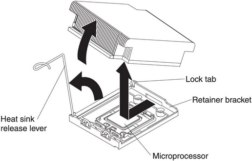
- Release the microprocessor retention latch by pressing down on the end, moving it to the side, and releasing it to the open position.
- Open the microprocessor bracket frame by lifting up the tab on the top edge. Keep the bracket frame in the open position.
Figure 2. Microprocessor bracket frame disengagement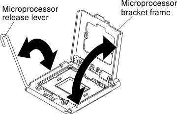
- Locate the microprocessor installation tool that comes with the new microprocessor.
- Twist the handle on the microprocessor tool counterclockwise so that it is in the open position.
Figure 3. Installation tool handle adjustment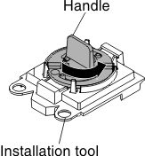
- Align the installation tool with the alignment pins on the microprocessor socket and lower the tool down over the microprocessor.
Figure 4. Installation tool alignment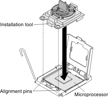
- Twist the handle on the installation tool clockwise and lift the microprocessor out of the socket.
Figure 5. Installation tool handle adjustment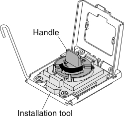
- Carefully lift the microprocessor straight up and out of the socket, and place it on a static-protective surface. Remove the microprocessor from the installation tool by twisting the handle counterclockwise.
- If you do not intend to install a microprocessor in the socket, install the socket dust cover that you removed in step Step 4.b in “Installing a microprocessor and heat sink” on the socket.
The pins on the socket are fragile. Any damage to the pins may require replacing the system board.
If you are instructed to return the microprocessor, follow all packaging instructions, and use any packaging materials for shipping that are supplied to you.


