Rear view
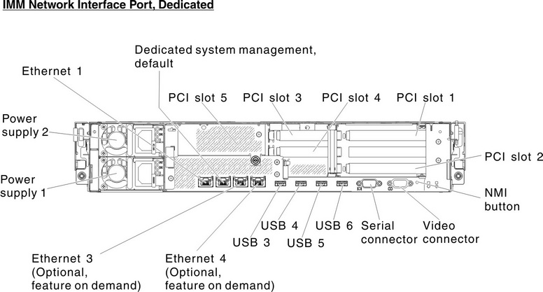
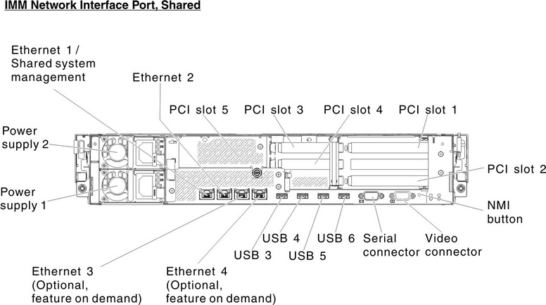
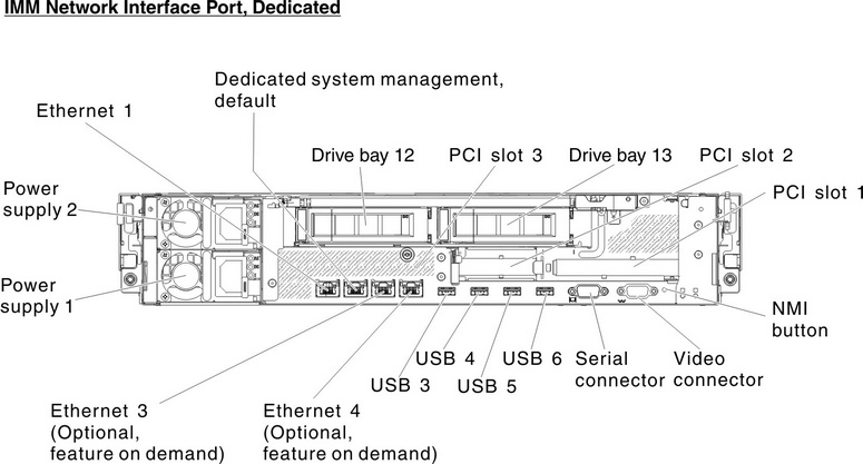
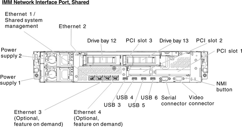
The following shows the connectors on the rear of the server.
The server configuration may be of the following two:
Illustration when no rear hard disk drive is installed in server. The PCI riser card assembly for this server configuration is 2U.
Ethernet and systems-management connectors:
IMM2 dedicated mode (default):
In this mode, which is the default setting for the server, the Ethernet 2 connector connects to a network for full systems-management information control. A dedicated management network provides additional security by physically separating the management network traffic from the production network. In dedicated mode the external port used by the integrated baseboard management controller (iBMC) still shares with the onboard host NIC, but does not allow production network activity. Meanwhile, the Ethernet 1, Ethernet 3 and Ethernet 4 connectors are used to connect to the production network. See Using the Setup utility for more information.
IMM2 shared mode:
In this mode, the Ethernet 1 connector is used to connect to a network for full systems-management information control and production network. See Using the Setup utility for more information.
| UEFI mode | Ethernet Port 1 | Ethernet Port 2 | Ethernet Port 3 (optional) | Ethernet Port 4 (optional) |
|---|---|---|---|---|
| IMM network interface port dedicated (default) | Production Ethernet | IMM2 dedicated (please see note) | Production Ethernet | Production Ethernet |
| IMM network interface port shared | Shared - Production Gb Ethernet and IMM2 (please see note) | Production Ethernet | Production Ethernet | Production Ethernet |
Note The IMM network is limited to 100 Mbps full duplex. | ||||
- PCI slot connectors:
- For 2U PCI riser card assembly:
- PCI slot 1: Insert a full-height, full-length PCI Express adapter into this slot.
- PCI slot 2: Insert a full-height, half-length PCI Express adapter into this slot.
- PCI slot 3: Insert a low-profile PCI Express adapter into this slot.
- PCI slot 4: Insert a low-profile PCI Express adapter into this slot.
- PCI slot 5: Insert a low-profile PCI Express adapter into this slot.
- For 1U PCI riser card assembly:
- PCI slot 1: Insert a full-height, half-length PCI Express adapter into this slot.
- PCI slot 2: Insert a low-profile PCI Express adapter into this slot.
- PCI slot 3: Insert a low-profile PCI Express adapter into this slot.
- For 2U PCI riser card assembly:
- USB connectors: Connect a USB device, such as USB mouse or keyboard to either of these connectors.
- Power supplies: Each power supply has a dc power LED and an ac power LED. When the dc power LED is lit, it indicates that the power supply is supplying adequate dc power to the system. During normal operation, both the ac and dc power LEDs are lit. For any other combination of LEDs, see Power-supply LEDs.
- NMI button: Press this button to force a nonmaskable interrupt to the microprocessor. It allows you to blue screen the server and take a memory dump (use this button only when directed by the service support). You might have to use a pen or the end of a straightened paper clip to press the button.
- Serial connector: Connect a 9-pin serial device to this connector. The serial port is shared with the integrated management module II (IMM2). The IMM2 can take control of the shared serial port to perform text console redirection and to redirect serial traffic.
- Video connector: Connect a monitor to this connector. The video connectors on the front and rear of the server can be used simultaneously.NoteThe maximum video resolution is 1600 x 1200 at 75 Hz.The following illustration shows the LEDs on the rear of the server.
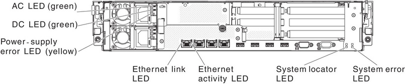
- Ethernet activity LEDs: When these LEDs are lit, they indicate that the server is transmitting to or receiving signals from the Ethernet LAN that is connected to the Ethernet port.
- Ethernet link LEDs: When these LEDs are lit, they indicate that there is an active link connection on the 10BASE-T, 100BASE-TX, or 1000BASE-TX interface for the Ethernet port.
- AC power LED: Each hot-swap power supply has an AC power LED and a DC power LED. When the AC power LED is lit, it indicates that sufficient power is coming into the power supply through the power cord. During typical operation, both the AC and DC power LEDs are lit. For any other combination of LEDs, see Power-supply LEDs.
- DC power LED: Each hot-swap power supply has a DC power LED and an AC power LED. When the DC power LED is lit, it indicates that the power supply is supplying adequate DC power to the system. During typical operation, both the AC and DC power LEDs are lit. For any other combination of LEDs, see Power-supply LEDs.
- Power-supply error LED: When the power-supply error LED is lit, it indicates that the power supply has failed.
- System-locator LED: Use this LED to visually locate the server among other servers. You can use Systems Director or IMM2 web interface to light this LED remotely.
- System-error LED: When this LED is lit, it indicates that a system error has occurred. An LED on the light path diagnostics panel is also lit to help isolate the error.