Standard I/O book
Use this information to for an overview of the system standard I/O book.
The components in the server standard I/O book are the minimum set of I/O components to form a server. The standard I/O book is not a hot-swap module. Therefore, you must power the server off and disconnect all power cords before you install and remove components from the standard I/O book.
Note
- If you are installing external RAID adapters that comes with a flash power module, the adapters must be installed in PCIe slots 7, 8, and 9 in the standard I/O book. Install the adapter flash power modules in the slots in the air baffle in the standard I/O book. Other PCIe adapters that do not come with a flash power module can also be installed in the standard I/O book.
- You can install up to three flash power modules in the standard I/O book.
- You can install only ML2 Ethernet adapters in PCIe slot 10 of the standard I/O book. See Supported ML2 (Ethernet) adapters for more information about the Ethernet adapters.
- The standard I/O book is connected to microprocessors 1 and 2. The standard I/O book PCIe buses are also connected to microprocessors 1 and 2.
The following is an illustration of the standard I/O book:
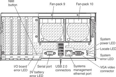
- 3V battery error LED: When this LED is lit, it indicates that a standard I/O book battery error has occurred.
- Ethernet connectors: Use either of these connectors to connect the server to a network. When you use the Ethernet 1 connector, the network can be shared with the IMM through a single network cable.
- Ethernet activity LEDs: When these LEDs are lit, they indicate that the server is transmitting to or receiving signals from the Ethernet LAN that is connected to the Ethernet port.
- Ethernet link LEDs:When these LEDs are lit, they indicate that there is an active link connection on the 100BASE-TX, 1000BASE-TX, or 10GBASE-TX interface for the Ethernet port.
- Ethernet adapter slots: Insert the dual-port or quad-port Ethernet adapters into these slots.
- I/O board error LED: When this LED is lit, it indicates that an error has occurred on the standard I/O book board.
- Locate LED: Use this LED to visually locate the server among other servers. You can use management software, such as Lenovo XClarity Administrator software, to light this LED remotely. IMM can also be used to turn this LED on and off. This LED is functionally equivalent to the locate LED on the front of the server.
- NMI button: Press this button to force a nonmaskable interrupt to the microprocessor. You might have to use a pen or the end of a straightened paper clip to press the button. You can also use it to force a blue-screen memory dump. Use this button only when you are directed to do so by Lenovo Support.
- Serial connector: Connect a 9-pin serial device to this connector. The serial port is shared with the integrated management module (IMM). The IMM can take control of the shared serial port to redirect serial traffic, using Serial over LAN (SOL).
- System-error LED: When this LED is lit, it indicates that a system error has occurred. An LED on the front operator panel is also lit to help isolate the error. This LED is functionally equivalent to the system-error LED on the front of the server.
- Systems-management Ethernet connector: Connect to this connector to manage the server, by using a dedicated management network. If you use this connector, the IMM cannot be accessed directly from the production network. A dedicated management network provides additional security by physically separating the management network traffic from the production network. You can use the Setup utility to configure the server to use a dedicated systems-management network or a shared network.
- USB 2.0 connectors: Connect a USB device, such as a USB mouse, keyboard, or other device, to any of these connectors.
- Video connector: Connect a monitor to this connector. The video connectors on the front and rear of the server can be used simultaneously.NoteThe maximum video resolution is 1600 x 1200 at 75 Hz.
The following is an illustration of the standard I/O book board:
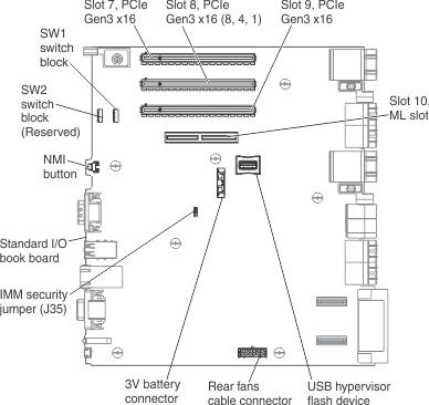
The server standard I/O book board provides the following slots, connectors, and integrated features:
- Integrated Management Module v.2 (IMM2)
- Real Time Management Module (RTMM)
- One ML adapter slot
- Three PCIe Gen3 slots (8 gigatransfers per second (GT/s))
- Five USB 2.0 connectors
- One internal USB 2.0 connector for Hypervisor flash USB device
- Four rear USB 2.0 connectors
- Two Trusted Platform Modules (TPM)
The standard I/O book is connected to compute book 1 and compute book 2. The standard I/O book PCIe buses are also connected to compute books 1 and 2.
Give documentation feedback