Installing a 1400-watt or 900-watt hot-swap power supply
Use this information for installation instructions and notes that you need to consider when you install 1400-watt or 900-watt ac hot-swap power supplies in the server.
- If you install additional power supplies or different power supplies, place the power rating label that comes with the new power supply option on the rear of the server.
- Four 900-watt or four 1400-watt hot-swap power supplies fed from a 110 V input source provides N+N redundancy support for limited configurations (per 4-socket node).
- Four 1400-watt hot-swap power supplies fed from a 220 V ac input source provides N+N redundancy support for a full configuration (per 4-socket node).
- The power supply bays are divided into two power domains. Power supply bays 1 and 3 are in power domain A and power supply bays 2 and 4 are in power domain B.
- To confirm that the server supports the power supply that you are installing, see the Lenovo ServerProven website.
- For more notes and information that you must consider when you install power supplies in the server, see Installing power supplies.
- The following table lists the population sequence for the supported power supply configurations. These configurations apply for each 4-socket node of the 8-socket server.
Table 1. Population sequence for the supported power supply configurations for each 4-socket node. Supported power supply configurations installation sequence for each 4-socket node
Power supply configuration Notes: 1 power supply The power supply should be installed in bay 3. This configuration does not support power supply redundancy. A power supply filler must be installed in bays 1, 2, and 4. 2 power supplies The power supplies should be installed in bays 2 and 3 with each supply on separate power feeds for feed redundancy. Both power supplies must be the same type (that is, the same wattage, ac power supplies, or dc power supplies). A power supply filler must be installed in bays 1 and 4. 4 power supplies Power supplies 1, 2, 3, and 4 must be the same input type (that is, all ac power supplies or all dc power supplies). - If you mix 900-watt and 1400-watt power supplies in the server, the power supplies must be installed as listed below:
Table 2. Population sequence when mixing 900-watt and 1400-watt ac power supplies in a four-power supply configuration (per 4-socket node). Population sequence when mixing 900-watt and 1400-watt ac power supplies in a four-power supply configuration (per 4-socket node)
NoteIf you are using two power input feeds, connect power supplies 1 and 3 to input feed A and power supplies 2 and 4 to input feed B.Power supply population sequence Power supply wattage Bays 1 and 4 900-watt Bays 2 and 3 1400-watt OR Bays 1 and 4 1400-watt Bays 2 and 3 900-watt - The following table lists the supported ac power supply configurations at both 220 V ac and 110 V ac. :
Table 3. Supported ac power supply configurations at both 220 V ac and 110 V ac for each 4-socket node. Two column table with headers that shows the supported ac power supply configurations at both 220 V ac and 110 V ac for each 4-socket node
Number of power supplies Power supply wattage One 900-watt One 1400-watt Two 900-watt Two 1400-watt Four Two 900-watt and two 1400-watt Four 900-watt Four 1400-watt
Hazardous voltage, current, and energy levels are present inside any component that has this label attached. There are no serviceable parts inside these components. If you suspect a with one of these parts, contact a service technician.
To install a hot-swap power supply, complete the following steps:
- Before you begin, read Safety and Installation guidelines.
- Touch the static-protective package that contains the power supply to any unpainted metal surface on the server; then, remove the power supply from the package and place it on a static-protective surface.
- If you are installing the power supply into an empty bay, remove the power-supply filler panel from the power-supply bay.
- Use one of the following procedures to install the power supply.
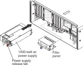
- To install a 1400-watt power supply, complete the following steps:
- Grasp the handle on the rear of the power supply and slide the power supply forward into the power-supply bay until it clicks. Make sure that the power supply connects firmly into the power-supply connector.
- Go to step 4.
- Grasp the handle on the rear of the power supply and slide the power supply forward into the power-supply bay until it clicks. Make sure that the power supply connects firmly into the power-supply connector.
- To install a 900-watt power supply, complete the following steps:
- Insert the power-supply spacer into the left side (against the bay wall) of the power-supply bay and slide it in until it snaps into place on tabs on the side of the bay.
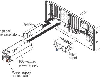
- Grasp the handle on the rear of the power supply and slide the power supply forward into the power-supply bay (next to the spacer) until it clicks into place. Make sure that the power supply connects firmly into the power-supply connector.
- Go to step 4.
- Insert the power-supply spacer into the left side (against the bay wall) of the power-supply bay and slide it in until it snaps into place on tabs on the side of the bay.
- To install a 1400-watt power supply, complete the following steps:
- Route the power cord through the cable hook-and-loop on the rear of the server so that it does not accidentally become unplugged.
- Connect the power cord for the new power supply to the power-cord connector on the power supply.
- Connect the other end of the power cord to a properly grounded electrical outlet.
- Make sure that the ac power LED on the power supply is lit, indicating that sufficient power is being supplied to the power supply through the power cord. During normal operation, both the ac and the dc power LEDs are lit. For any other combination of LEDs, see Power-supply LEDs. Make sure that no error LEDs are lit.
- Restart the server. Confirm that it starts correctly and recognizes the newly installed device, and make sure that no error LEDs are lit.