Installing a memory module
Use these instructions to install memory modules in the blade server.
The blade server has a total of twelve direct inline memory module (DIMM) slots. The blade server supports very low profile (VLP) DDR3 DIMMs with error code correction (ECC) in 1 GB, 2 GB, 4 GB, 8 GB, and 16 GB capacities. For a list of supported DIMMs for the blade server, see Parts listing.
After you install or remove a DIMM, you must change and save the new configuration information by using the Setup utility. When you turn on the blade server, a message indicates that the memory configuration has changed. Start the Setup utility and select Save Settings (see Setup utility menu for more information) to save changes.
The memory is accessed internally through the system using six channels. Each channel contains two DIMM connectors. The following table lists each channel and which DIMM connectors belong to the channel.
| Memory channel | DIMM connector |
|---|---|
| Channel 0 | DIMM connector 1 and 2 |
| Channel 1 | DIMM connector 5 and 6 |
| Channel 2 | DIMM connector 3 and 4 |
| Channel 3 | DIMM connector 7 and 8 |
| Channel 4 | DIMM connector 11 and 12 |
| Channel 5 | DIMM connector 9 and 10 |
Depending on the memory mode that is set in the Setup utility, the blade server can support a minimum of 1 GB and a maximum of 48 GB of system memory on the system board in a blade server with one processor. If two microprocessors are installed, the blade server can support a minimum of 2 GB and a maximum of 96 GB of system memory. There are two different memory modes:
- Independent channel mode: Independent channel mode gives a maximum of 96 GB of usable memory with one CPU installed, and 192 GB of usable memory with 2 CPUs installed (using 16 GB DIMMs). The DIMMs can be installed without matching sizes. See the table below for the memory installation order.
Table 2. System memory configuration for independent channel mode (1 microprocessor) Installed memory DIMM socket 1 2 3 4 5 6 7 8 9 10 11 12 1 DIMM X 2 DIMMs X X 3 DIMMs X X X 4 DIMMs X X X X 5 DIMMs X X X X X 6 DIMMs X X X X X X Table 3. System memory configuration for independent channel mode (2 microprocessors) Installed memory DIMM socket 1 2 3 4 5 6 7 8 9 10 11 12 2 DIMMs X X 3 DIMMs X X X 4 DIMMs X X X X 5 DIMMs X X X X X 6 DIMMs X X X X X X 7 DIMMs X X X X X X X 8 DIMMs X X X X X X X X 9 DIMMs X X X X X X X X X 10 DIMMs X X X X X X X X X X 11 DIMMs X X X X X X X X X X X 12 DIMMs X X X X X X X X X X X X - Mirrored channel mode: In mirrored channel mode, channels 2 and 5 are unused. The memory contents on channel 0 are duplicated in channel 1, and the memory contents of channel 3 are duplicated in channel 4. The effective memory available to the system is only half of that installed. The maximum available memory (with 16 GB DIMMs) is 32 GB for a single CPU system and 64 GB for a dual CPU system.ImportantThe memory configuration of channel 0 must match that of channel 1, and the memory configuration of channel 3 must match that of channel 4. For example, if a 4 GB Dual Rank DIMM is installed into the DIMM2 connector, then a 4 GB Dual Rank DIMM must also be installed into the DIMM6 connector.
Table 1 lists each channel and which DIMM connectors belong to the channel. The following table shows the order that memory DIMMs are installed to use a mirrored channel mode.
Table 4. System memory configuration for mirrored channel mode (1 microprocessor) Installed memory DIMM socket 1 2 3 4 5 6 7 8 9 10 11 12 2 DIMMs X X 4 DIMMs X X X X Table 5. System memory configuration for mirrored channel mode (2 microprocessors) Installed memory DIMM socket 1 2 3 4 5 6 7 8 9 10 11 12 4 DIMMs X X X X 6 DIMMs X X X X X X 8 DIMMs X X X X X X X X - Spare channel mode: In spare channel mode, channel 2 is the spare of the active channels 0 and 1. The spare channel is not available as active memory. The maximum memory available (with 16 GB DIMMs) is 64 GB in a single CPU system and 128 GB in a dual CPU system. All three channels must have identical population with regards to size and organization. DIMMs within a channel do not have to be identical. The population ordering for spare channel mode is shown in the table below.NoteSpare channel mode is only supported if the blade server has an Intel Xeon 5600 series microprocessor. Use the Setup utility to view the system summary and verify the type of microprocessor installed in your blade server (see
Using the Setup utility). The following table shows the order that memory DIMMs are installed to use spare channel mode.
Table 6. System memory configuration for spare channel mode (1 microprocessor) Installed memory DIMM socket 1 2 3 4 5 6 7 8 9 10 11 12 3 DIMMs X X X 6 DIMMs X X X X X X Table 7. System memory configuration for spare channel mode (2 microprocessors) Installed memory DIMM socket 1 2 3 4 5 6 7 8 9 10 11 12 6 DIMMs X X X X X X 9 DIMMs X X X X X X X X X 12 DIMMs X X X X X X X X X X X X
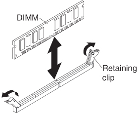
To install a DIMM, complete the following steps:
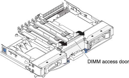
- If you are installing a DIMM in DIMM connector seven through twelve, use your fingers to lift the DIMM access door.
- To install the DIMMs, repeat the following steps for each DIMM that you install: