Installing a memory module
Use these instructions to install memory modules in the blade server.
The blade server has a total of twelve direct inline memory module (DIMM) slots. The blade server supports very low profile (VLP) DDR3 single-rank, dual-rank, or quad-rank DIMMs with error code correction (ECC) in 2 GB, 4 GB, 8 GB, and 16 GB capacities. For a list of supported DIMMs for the blade server, see Parts listing.
- DIMM:
- IBM option part number 90Y3221 (CRU part number 90Y3223) - 16 GB 4R x 4 1066 MHz VLP RDIMM 1.35V.
- Limitation:
- Not supported with two 95W microprocessors and two DIMMs per channel in BladeCenter E.
- Supported with one 95W microprocessor and two DIMMs per channel (up to 6 DIMMs attached to microprocessor 1) or two 95W microprocessors with one DIMM per channel (up to 3 DIMMs attached to microprocessor 1 and 3 DIMMs attached to microprocessor 2) with DIMM fillers removed in empty DIMM connectors of microprocessor 2.
After you install or remove a DIMM, you must change and save the new configuration information by using the Setup utility. When you turn on the blade server, a message indicates that the memory configuration has changed. Start the Setup utility and select Save Settings (see Setup utility menu for more information) to save changes.
The memory is accessed internally through the system using three channels per microprocessor. Each channel contains two DIMM connectors. The following table lists each channel and which DIMM connectors belong to the channel.
| Memory channel | DIMM connector (microprocessor 1) | DIMM connector (microprocessor 2) |
|---|---|---|
| Channel 1 | 1 and 2 | 7 and 8 |
| Channel 2 | 3 and 4 | 9 and 10 |
| Channel 3 | 5 and 6 | 11 and 12 |
Depending on the memory mode that is set in the Setup utility, the blade server can support a minimum of 2 GB and a maximum of 96 GB of system memory on the system board in a blade server with one microprocessor. If two microprocessors are installed, the blade server can support a minimum of 4 GB and a maximum of 192 GB of system memory. There are three different memory modes:
- Independent channel mode: Independent channel mode gives a maximum of 96 GB of usable memory with one microprocessor installed, and 192 GB of usable memory with two microprocessors installed (using 16 GB DIMMs). The DIMMs can be installed without matching sizes. See the table below for the memory installation order.
Table 2. Independent channel mode DIMM installation sequence One microprocessor installed Two microprocessors installed DIMM connectors 5, 3, 1, 6, 4, 2 DIMM connectors 5, 11, 3, 9, 1, 7, 6, 12, 4, 10, 2, 8 - Rank sparing mode: In rank-sparing mode, one memory DIMM rank serves as a spare of the other ranks on the same channel. The spare rank is held in reserve and is not used as active memory. The spare rank must have identical or larger memory capacity than all the other active memory ranks on the same channel. After an error threshold is surpassed, the contents of that rank is copied to the spare rank. The failed rank of memory is taken offline, and the spare rank is put online and used as active memory in place of the failed rank.NoteRank sparing mode is supported if the blade server meets one of the following memory requirements:
- One quad-rank DIMM
- More than one DIMM per channel
- An even number of single-rank or dual-rank DIMMs
For rank sparing mode memory installation order on a blade server with quad-rank DIMMs, see Independent channel mode DIMM installation sequence.
The following tables show the order that single-rank or dual-rank DIMMs are installed to use rank sparing mode:Table 3. Rank sparing mode DIMM installation sequence for single-rank or dual-rank DIMMs (one microprocessor) DIMM pair DIMM connector First 5, 6 Second 3, 4 Third 1, 2 Table 4. Rank sparing mode DIMM installation sequence for single-rank or dual-rank DIMMs (two microprocessors) DIMM pair DIMM connector First 5, 6
11, 12
Second 3, 4 Third 9, 10 Fourth 1, 2 Fifth 7, 8 NoteIn rank sparing mode, if any of the installed DIMMs does not meet the requirements listed above, the system is executed as independent channel mode. - Mirrored channel mode: In mirrored channel mode, memory is installed in pairs. Each DIMM in a pair must be identical in capacity, type, and rank count. The channels are grouped in pairs with each channel receiving the same data. One channel is used as a backup of the other, which provides redundancy. The memory contents on channel 2 are duplicated in channel 3. Channel 1 DIMM connectors 1, 2, 7, and 8 are not used in mirrored channel mode. The maximum available memory (with 16 GB DIMMs) is 32 GB for a single microprocessor system and 64 GB for a dual microprocessor system.ImportantThe memory configuration of channel 2 must match that of channel 3. For example, if a 4 GB Dual Rank DIMM is installed into the DIMM connector 3 (channel 2), then a 4 GB Dual Rank DIMM must also be installed into the DIMM connector 5 (channel 3).
Memory channel configuration lists each channel and which DIMM connectors belong to the channel. The following table shows the order that memory DIMMs are installed to use mirrored channel mode.
Table 5. System memory configuration for mirrored channel mode (one microprocessor) DIMM pair DIMM connector First 3 and 5 Second 4 and 6 Table 6. System memory configuration for mirrored channel mode (two microprocessors) DIMM pair DIMM connector First 3 and 5, 9 and 11 Second 4 and 6 Third 10 and 12
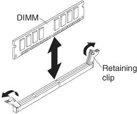
To install a DIMM, complete the following steps:
- To install the DIMMs, repeat the following steps for each DIMM that you install: