Introduction
The Lenovo Flex System Carrier-Grade chassis Type 7385 is an 11U NEBS level 3 certified server platform suitable for central offices and rugged environments. It is a compact, high-density, high-performance, rack-mounted, scalable server platform system with integrated chassis management. The 11U Flex System Carrier-Grade chassis is suitable for installation in Network Telecommunication Facilities.
The Flex System Carrier-Grade chassis has fourteen node bays that support up to fourteen 1-bay compute nodes or up to seven 2-bay compute nodes when the shelves are removed from the chassis. You can use both 1-bay and 2-bay compute nodes to meet your specific hardware needs. .
The compute nodes share common resources, such as power, cooling, management, and I/O resources in the chassis.
- A 1-bay compute node occupies one node bay in the chassis.
- A 2-bay compute node occupies two adjacent node bays (horizontally) in the chassis and requires the chassis shelf to be removed prior to installation.
The Flex System Carrier-Grade chassis can support the following components:
- Up to fourteen 1-bay compute nodes or up to seven 2-bay compute nodes with the shelves removed.
- Up to six -48 V to -60 V dc power supplies. 200-240 V ac power supplies are also available.
- Up to ten fan modules (two 40 mm fan modules and eight 80 mm fan modules).
- Four I/O modules (two redundant pairs), with the following features in each module:
- A four-lane physical interconnect that supports speeds up to 16 Gbps, four-lanes to each single node bay or eight-lanes to each full-width node bay (two adjacent bays), 16 Gbps per lane. The four lanes support 4x10 Gbps (40 Gbps) or Fourteen Data Rate InfiniBand at 56 Gbps.
- Four x1 ports or a single x4 port on each compute node
- Up to 16 logical I/O modules (four per physical I/O module)
- Two Lenovo Flex System Chassis Management Modules (CMMs) for redundancy. A CMM provides single-chassis management support.
- Two fan logic modules, which detect fan module presence and provide a communication path to the fan modules.
- Two fan distribution cards, which pass the power and signals from the midplane to the fan modules and the fan logic modules.
- One rear LED card, which stores the vital product data (VPD) of the chassis components.
X-Architecture
The Flex System Carrier-Grade chassis is an X-Architecture system that uses proven innovative technologies to build powerful, scalable, and reliable compute node platforms. It provides features such as Predictive Failure Analysis (PFA) and real-time diagnostics.
Compute node expansion capabilities
You can install up to fourteen 1-bay compute nodes or up to seven 2-bay compute nodes in the chassis. The compute nodes have connectors for additional optional devices that you can use to add capabilities to the compute nodes. For example, you can install optional I/O expansion adapters to add network interfaces or storage through the I/O modules.
Hot-swap capabilities
All component bays in the chassis are hot-swappable. For example, you can add, remove, or replace a compute node, I/O module, Chassis Management Module, fan logic module, fan module, or power supply without disconnecting the power from the chassis.
High-availability design
The following components in the chassis enable continued operation if one of the components fails:Power supplies
The power supplies support a single power domain that provides dc power to all of the chassis components. If a power supply fails, the other power supplies can continue to provide power. For power redundancy, additional power supplies can be installed.NoteThe power management policy that you have implemented for the chassis determines the result of a power-supply failure.I/O modules
The I/O module bays provide a four-lane physical interface to each 1-bay compute node that supports speeds up to 56 Gbps. The I/O modules must be installed in pairs if you want them to be redundant.
Fan modules
The fan modules provide cooling to all of the chassis components.
Fan logic modules
The fan logic modules enable the Chassis Management Module to monitor the fans and control fan speed.
Chassis midplane
The chassis midplane provides the following features:
- Redundant high-speed serialize/deserialize (SERDES) interconnects between compute nodes and I/O modules
- I2C communication paths between the CMM and all devices in the chassis
- 1 Gb Ethernet communication paths between the CMM and all compute nodes and I/O modules
- Power distribution to all nodes and modules
The midplane provides hot-swap connectors for the following components:- Fourteen 1-bay compute nodes or seven 2-bay compute nodes
- Four I/O modules
- Two CMMs
- Six power supplies
- Ten fan modules
- Two fan logic modules
Systems management
The Lenovo XClarity Administrator, if available, is a virtual appliance that you can use to manage multiple Flex System Carrier-Grade chassis in a secure environment. The Lenovo XClarity Administrator provides a central interface to perform the following functions for all managed endpoints:- User management
- Hardware monitoring and management
- Configuration management
- Operating system deployment
- Firmware management
The Lenovo Flex System Chassis Management Module (Chassis Management Module or CMM) provides single-chassis management. The Chassis Management Module is used to communicate with the system-management processor in each compute node to provide system monitoring, event recording, and alerts and to manage the chassis, its devices, and the compute nodes. The chassis supports up to two CMMs. If one CMM fails, the second CMM can detect its inactivity, activate itself, and take control of the system without any disruption. For more information about the CMM, see the CMM2 information page.
| Component | Bay |
|---|---|
| Two power supplies | Power-supply bays 1 and 4 |
| Two 40 mm fan modules | Fan bays 5 and 10 |
| Four 80 mm fan modules | Fan bays 1, 2, 6, and 7 |
| Two fan logic modules | Fan logic bays 1 and 2 |
| One Chassis Management Module | CMM bay 1 |
| One I/O module | I/O bay 1 |
| One compute node | Node bays 1 - 14 |
| ||||||||||
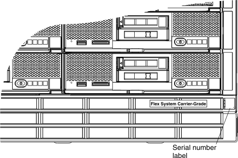
The serial number and model number are on the top, front, and rear of the chassis. The following illustration shows the location of the label on the front of the chassis.
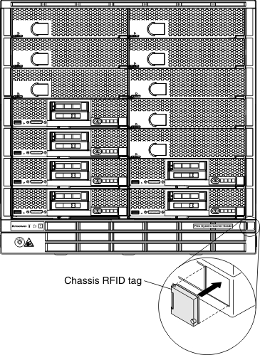
If the chassis comes with an RFID tag, it is attached to the lower-right corner of the bezel. The following illustration shows the location of the RFID tag on the front of the chassis.