Replacing an adapter in a riser-card assembly
Use this section to replace an adapter in a riser-card assembly.
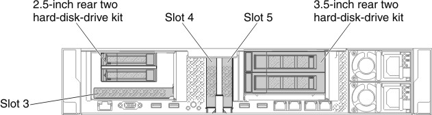
The following illustration shows the locations of the adapter expansion slots from the rear of the server.
Figure 1. PCI riser-card adapter expansion slot locations
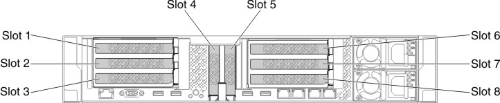
Figure 2. PCI riser-card adapter expansion slot locations
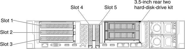
Figure 3. PCI riser-card adapter expansion slot locations
The following table describes the maximal card dimension supported in each slot.
| Riser-card assembly | Slot number | The maximal card dimension supported |
|---|---|---|
| Riser-card assembly 1 | 1 | Full height, up to full length |
| 2 | Full height, up to full length | |
| 3 | Full height, half length | |
| 4 | Low-profile | |
| 5 | Low-profile | |
| Riser-card assembly 2 | 6 | Full height, up to full length |
| 7 | Full height, up to full length | |
| 8 | Full height, half length |
The following notes describe the types of adapters that the server supports and other information that you must consider when you install an adapter:
- Locate the documentation that comes with the adapter and follow those instructions in addition to the instructions in this section.
- The server provides two internal SAS connectors and two SAS/SATA RAID riser-card slots on the system board. See System-board optional-device connectors for the location of the internal SAS/SATA RAID connector and riser-card slots. You can replace the ServeRAID SAS/SATA adapter with an optional ServeRAID SAS/SATA adapter in the slot. For configuration information, see the ServeRAID documentation at the Lenovo Support Portal.
- Do not set the maximum digital video adapter resolution above 1600 x 1200 at 75 Hz for an LCD monitor. This is the highest resolution that is supported for any add-on video adapter that you install in the server.
- Read the following table before installing memory modules when any Quadro adapters is installed.
Table 2. NVIDIA Quadro video adapter configurations. Description Supported maximum total memory size Grid K1 adapter 1 TB Grid K2 adapter 1 TB Tesla K40 adapter 1 TB - Do not install the following adapters in the slot 1.
Table 3. Non-supported adapters in the slot 1. Adapter description Option part number FRU part number Emulex 16Gb FC Single-port HBA for Lenovo System x 81Y1655 00D8546 Emulex 16Gb FC Dual-port HBA for Lenovo System x 81Y1662 00JY849 - Do not install the following adapters in the slot 3 and the slot 8.
Table 4. Non-supported adapters in the slot 3 and the slot 8. Adapter description Option part number FRU part number N2215 SAS/SATA HBA for System x 47C8675 47C8676 N2215 SAS/SATA HBA for System x 00AE912 00AE914 ServeRAID M5225-2GB SAS/SATA Controller for System x 00AE938 00AE939 Emulex Dual Port 10GbE SFP+ VFA IIIr for System x 00D8540 00D8543 Mellanox ConnectX-3 40GbE/ FOR IB VPI Adapter for System x 00D9550 00D9552 Broadcom NetXtreme 2x10GbE Base T Adapter for System x 44T1370 00E2714 Qlogic 8200 Dual PORT 10GbE SFP+ Adapter for System x 90Y4600 90Y4605 Broadcom NetXtrme Dual Port 10GbE SPG+ Adapter for System x 94Y5180 94Y5182 Mellanox ConnectX-3 10GbE Adapter for System x 00D9690 00D9692 Intel x520 Dual Port 10GbE SFP+ Adapter for System x 49Y7960 49Y7962 Emulex VFA5 2x10GbE SFP+ Adapter for System x 00JY830 00JY833 - Any high-definition video-out connector or stereo connector on any add-on video adapter is not supported.
- When you install any PCI adapter, the power cords must be disconnected from the power source before you remove the PCI Express riser-card assembly. Otherwise, the active power management event signal will be disabled by the system-board logic, and the Wake on LAN feature might not work. However, after the server is powered-on locally, the active power manager active power management event signal will be enabled by the system-board logic.
- When you install an Intel X540 ML2 Dual Port 10GbaseT Adapter (Option part number is 00D1994), you need to install the PCIe Thermal Solution Kit (Option part number: 00MU908) first to avoid the potential thermal issue.
- Support Intel MIC GPU cards (3120A and 7120A) up to 35C/3000ft, otherwise GPU card performance could be downgraded.
Attention
- Do not install over 3 ServeRAID M1215 SAS/SATA controllers in one system.
- Do not install the NVIDIA Grid Kx/Mxx, the NVIDIA Quadro Kxxxx or the NVIDIA Tesla Kxx adapter options in systems containing 1TB of system memory or more. If these options are installed in systems with 1TB of memory or more, it might cause undetected data corruption and system instability. These options are only supported in systems containing less than 1TB of memory. For more information, see RETAIN tip H213010 at http://www.ibm.com/support/entry/myportal/docdisplay?lndocid=migr-5096047.
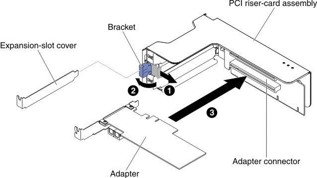
To replace an adapter, complete the following steps:
- Align the adapter with the PCI connector on the riser card and press the adapter firmly into the PCI connector on the riser card.Figure 4. Adapter installation
- If you are installing a full-height, full-length adapter, insert the shipping brackets.Figure 5. Full-height, full-length adapter
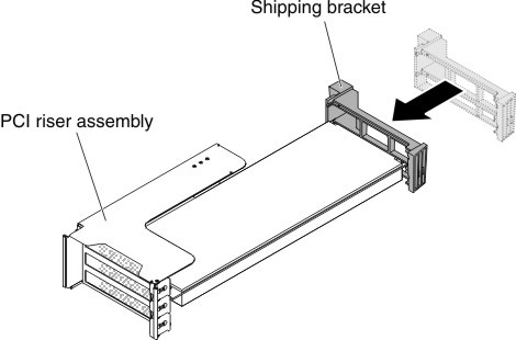
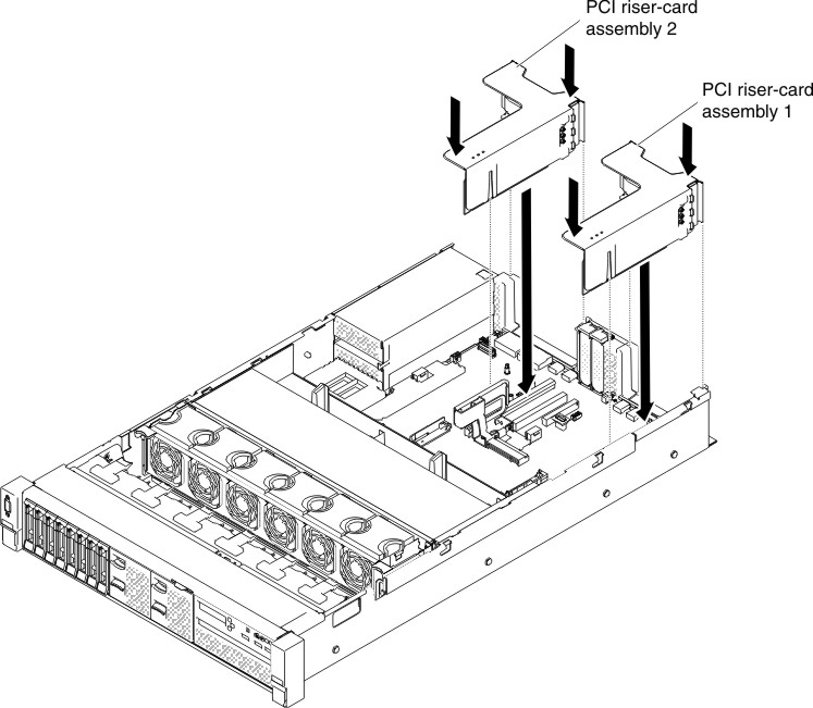
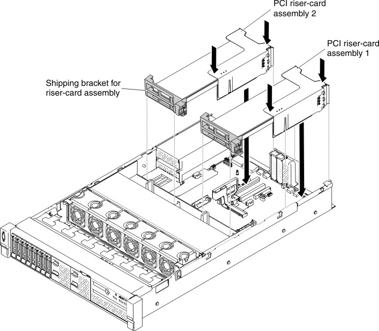
- Align the riser-card assembly with the selected PCI connector on the system board and align it with the slots on the chassis; then, lower it into the server and press down firmly until the riser-card assembly is seated correctly in the connector on the system board.
- For half-length and low profile adaptersFigure 6. Riser-card assembly installation - half-length and low profile adapters
- For full-height, full-length adaptersNoteShipping brackets are only included in the server that is pre-configured with full-height, full-length adaptersFigure 7. Riser-card assembly installation - full-height, full-length adapters
- For half-length and low profile adapters
Give documentation feedback