Replacing an adapter in a riser-card assembly
Use this section to replace an adapter in a riser-card assembly.
The following illustration shows the locations of the adapter expansion slots from the rear of the server.
Figure 1. PCI riser-card adapter expansion slot locations
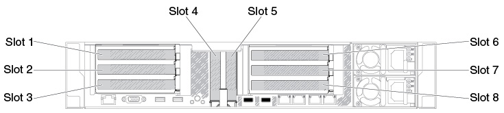
The following table describes the maximal card dimension supported in each slot.
| Riser-card assembly | Slot number | The maximal card dimension supported |
|---|---|---|
| Riser-card assembly 1 | 1 | Double height, up to full length |
| 3 | Full height, half length | |
| 4 | Low-profile | |
| 5 | Low-profile | |
| Riser-card assembly 2 | 6 | Double height, up to full length |
| 8 | Full height, half length |
The following notes describe the types of adapters that the server supports and other information that you must consider when you install an adapter:
- Locate the documentation that comes with the adapter and follow those instructions in addition to the instructions in this section.
- The server provides two internal SAS connectors and two SAS/SATA RAID riser-card slots on the system board. See System-board optional-device connectors for the location of the internal SAS/SATA RAID connector and riser-card slots.
- Do not set the maximum digital video adapter resolution above 1600 x 1200 at 75 Hz for an LCD monitor. This is the highest resolution that is supported for any add-on video adapter that you install in the server.
- Read the following table before installing memory modules when any NVIDIA adapters is installed.
Table 2. NVIDIA video adapter configurations. Description Supported maximum total memory size NVIDIA Tesla K8, K40c, and M60 (Active) 1 TB - Do not install the following adapters in the slot 3 and the slot 8.
Table 3. Non-supported adapters in the slot 3 and the slot 8. Adapter description Option part number FRU part number N2215 SAS/SATA HBA for System x 47C8675 47C8676 N2215 SAS/SATA HBA for System x 00AE912 00AE914 Intel x520 Dual Port 10GbE SFP+ Adapter for System x 49Y7960 49Y7962 - Any high-definition video-out connector or stereo connector on any add-on video adapter is not supported.
- When you install any PCI adapter, the power cords must be disconnected from the power source before you remove the PCI Express riser-card assembly. Otherwise, the active power management event signal will be disabled by the system-board logic, and the Wake on LAN feature might not work. However, after the server is powered-on locally, the active power manager active power management event signal will be enabled by the system-board logic.
To replace an adapter, complete the following steps:
- Align the adapter with the PCI connector on the riser card and press the adapter firmly into the PCI connector on the riser card.Figure 2. Adapter installation

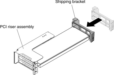
- If you are installing a full-height, full-length adapter, insert the shipping brackets.Figure 3. Full-height, full-length adapter
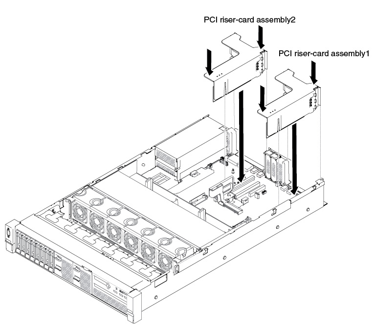
- Align the riser-card assembly with the selected PCI connector on the system board and align it with the slots on the chassis; then, lower it into the server and press down firmly until the riser-card assembly is seated correctly in the connector on the system board.
- For half-length and low profile adapters (for HX7510 only)Figure 4. Riser-card assembly installation - half-length and low profile adapters
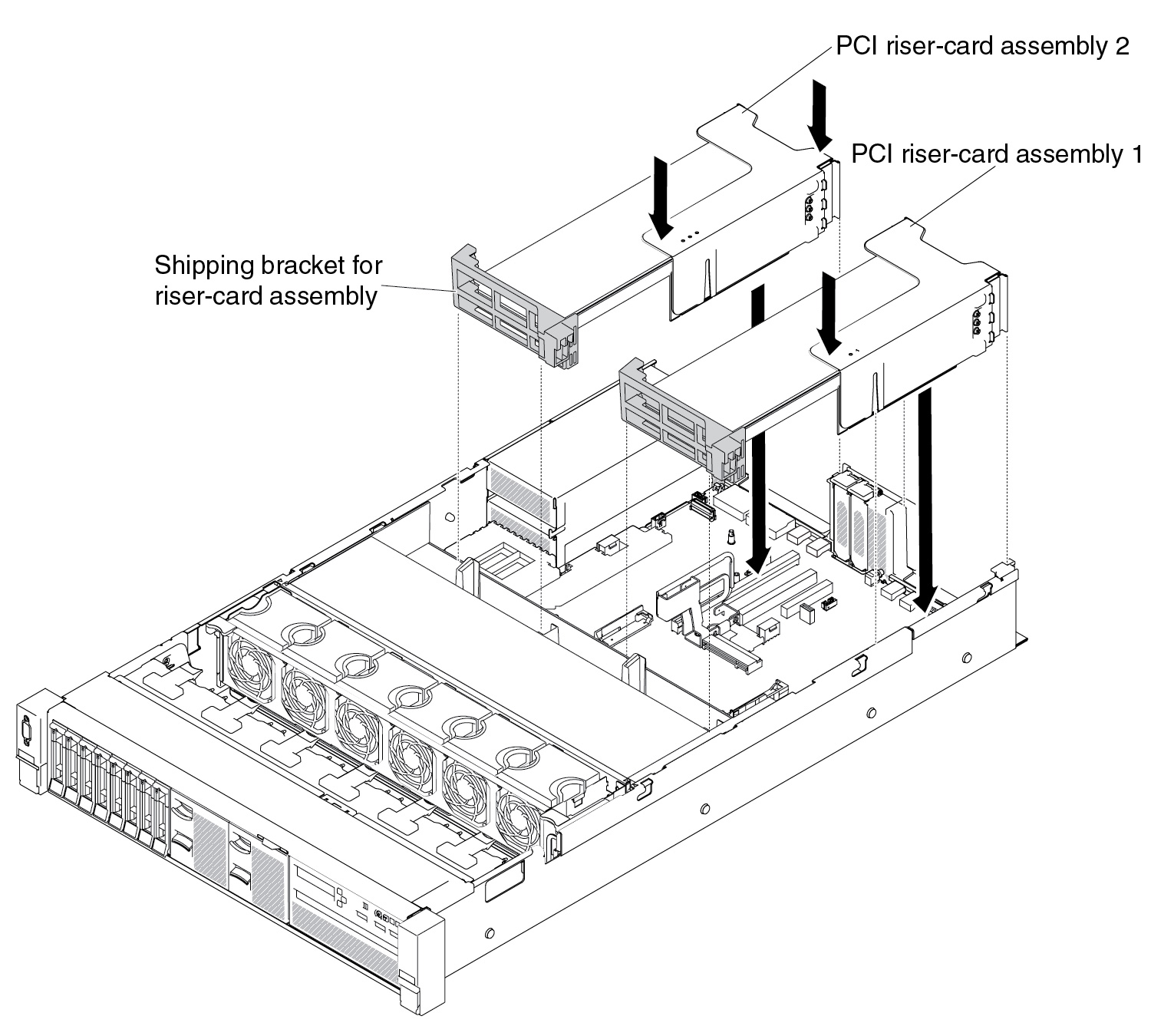
- For full-height, full-length adapters (for HX3510-G only)NoteShipping brackets are only included in the server that is pre-configured with full-height, full-length adaptersFigure 5. Riser-card assembly installation - full-height, full-length adapters
- For half-length and low profile adapters (for HX7510 only)
Give documentation feedback