Top view
This section contains information on the top view of the server.
Top view of 3.5-inch front drive configuration
Figure 1. Top view of 3.5-inch front drive configuration
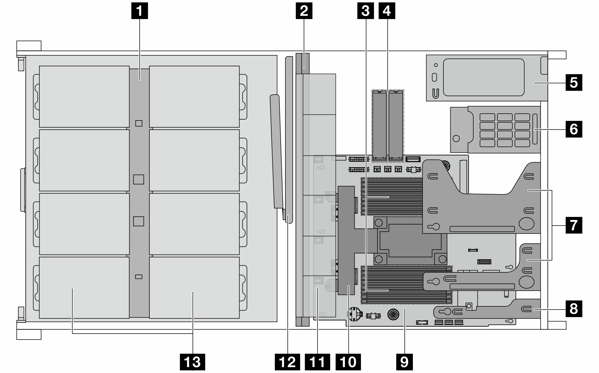
| 1 Front backplane | 8 DC-SCM |
| 2 Middle wall | 9 System board |
| 3 Memory modules | 10 Processor and heat sink assembly |
| 4 M.2 drive assembly | 11 System fan assembly |
| 5 Power supply units | 12 Cable management arm (CMA) |
| 6 Rear drive assemblies | 13 Front drives |
| 7 Riser assemblies |
Note
The illustration shows the server rear configuration with two riser assemblies. For details, see Rear view.
The illustration shows the location of certain parts. Some parts may not be supported at the same time within certain configuration(s).
Give documentation feedback