System-board switches
The following illustrations show the location of the switches on the server.
Note
If there is a clear protective sticker on the top of the switch blocks, you must remove and discard it to access the switches.
To gain access to the switches, remove DC-SCM first, see Remove the Datacenter Secure Control Module (DC-SCM).
Important
Before you change any switch settings or move any jumpers, turn off the server; then, disconnect all power cords and external cables. Review the following information:
- Any system-board switch or jumper block that is not shown in the illustrations in this document are reserved.
Figure 1. System-board switches
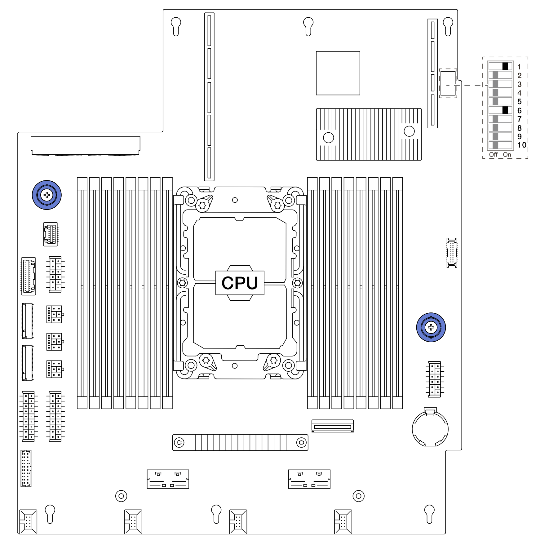
SW4 switch block
The following table describes the functions of the SW4 switch block on the system board.
| Switch-bit number | Switch name | Default position | Description |
|---|---|---|---|
| 1 SW4–1 | PVNN_PCH_AUX_VSET | On | Sets the voltage of PVNN_PCH_AUX when switched to On. |
| 2 SW4–2 | RST_RTCRST_N | Off | Clears CMOS. |
| 3 SW4–3 | FM_NO_REBOOT_SPKR | Off | Controls the TCO timer when running the ITP. |
| 4 SW4–4 | PD_MFG_MODE | Off | Sets manufactory mode for BIOS. |
| 5 SW4–5 | FM_ME_RCVR_N | Off | Recovers Intel ME. |
| 6 SW4–6 | FM_CPU0_SKTOCC_N | On | Bypasses the processor when running the ITP. |
| 7 SW4–7 | BMC_XDP_JTAG_SEL | Off | Selects BMC JTAG to the processor or CPLD. |
| 8 SW4–8 | FM_FORCE_PWRON_LVC3_R | Off | Forces power on for power measurement. |
| 9 SW4–9 | PD_ADR_COMPLETE | Off | Controls Asynchronous DRAM Refresh completion. |
| 8 SW4–10 | HW_ASD_EN | Off | Enables At-Scale Debug. |
Give documentation feedback