System-board connectors
The following illustrations show the internal connectors on the system board.
Figure 1. System-board connectors
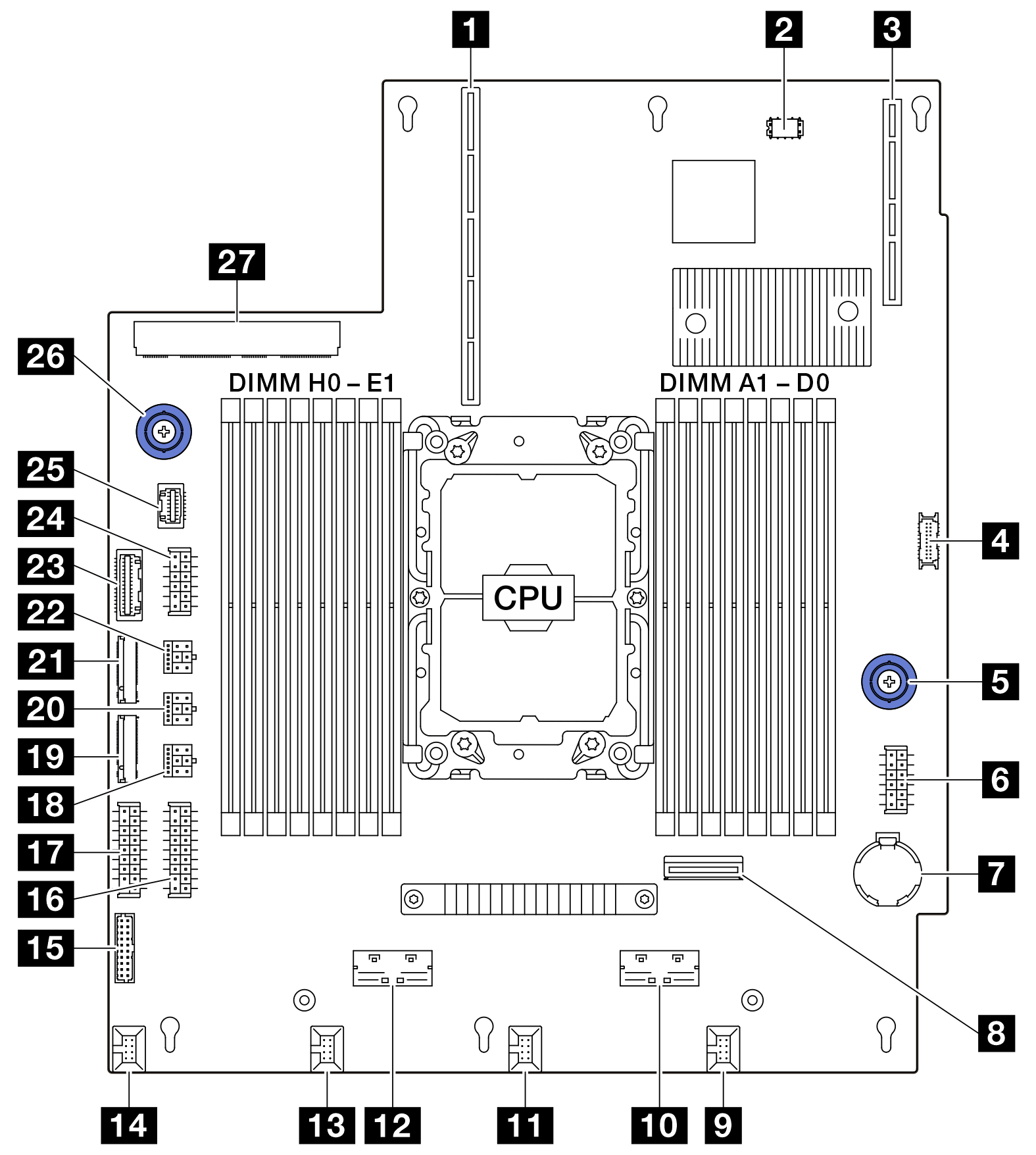
| 1 Riser 1 slot (PCIe × 24) | 15 Fan 4 & 5 connector |
| 2 VROC key connector | 16 PIB power connector 1 |
| 3 DC-SCM slot | 17 PIB power connector 0 |
| 4 Front panel connector | 18 Front BP power connector 3 |
| 5 System board handle | 19 NVMe M.2 connector 0 |
| 6 Riser 2 power connector | 20 Front BP power connector 2 |
| 7 Battery | 21 NVMe M.2 connector 1 |
| 8 MCIO 2 for riser 2 | 22 Front BP power connector 1 |
| 9 Fan 0 connector | 23 PIB signal connector |
| 10 MCIO 3 for riser 2 | 24 Rear BP power connector |
| 11 Fan 1 connector | 25 NCSI for PCIe NIC card |
| 12 MCIO 1 for NVMe SSD | 26 System board handle |
| 13 Fan 2 connector | 27 OCP connector |
| 14 Fan 3 connector |
Give documentation feedback