Enclosure Rear Overview
SMM2 information is displayed in this view.
Management Module
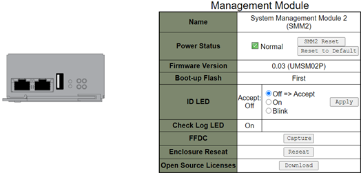
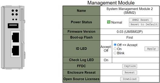
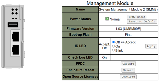
Name: System Management Module 2 (SMM2).
Power Status: Indicates the status of SMM2.
SMM2 Reset: After this button is clicked, SMM2 will be reset immediately and ready to operate in 90 seconds.
- Reset to Default: Restore the SMM2 settings to out-of-factory default, including:
SMTP
SNMP
PEF
Network Configuration
User Account
Account Security
Services
Web Certificate
NTP
Firmware version: The current firmware version.
Boot-up Flash: Indicates SMM2 current boot up bank. In normal operation, Boot-up flash should always be First. Only when the first flash has a hardware or firmware failure, SMM2 will switch to Second flash.
Identification LED (ID LED): This blue LED serves to visually locate an enclosure in the rack with the following three options available. To activate an option, choose it from the list and click on Apply or use the corresponding commands.
Turn Off
When this option is activated, SMM2 ID LED would first turn off the ID LED on all the compute nodes in the enclosure and enter the accept mode, in which the LED behavior is determined by the node ID LEDs.
Table 1. SMM2 ID LED accept mode behavior Node identification LEDs SMM2 identification LED All the node ID LEDs are off. Off No node ID LED is blinking, but one or more node ID LEDs are on. On One or more node ID LEDs are blinking. Blink NoteSMM2 ID LED is set in the accept mode by default.
See the “Front LEDs and buttons / Node operator panel” section in Maintenance Manual/Setup Guide/User Guide of your solution for more information about node ID LEDs.
Turn On
When this option is activated, all the node ID LEDs will be on except the blinking ones, which will remain blinking.
Blink
When this option is activated, all the node ID LEDs will be blinking regardless of previous status.
Check Log LED: Check Log LED will be on when an error event occurs. It will be turned off after the error event is de-asserted.
FFDC: The Fast Failure Data Collection (FFDC) instantly collects information about events and conditions that might lead up to a failure. Click on Capture, and the file used to analyze the problem can be downloaded from the web.
Enclosure Reseat: Click on Reseat, the enclosure will be powered off immediately and be powered on after 10 seconds.
NoteAfter you click on the button,Enclosure Reseat will go into effect immediately even when the nodes are still powered on. Open Source License: You can download the Open Source Licenses file that is used in Open Source packages in SMM2 by clicking on Download.
Current PSU
Current PSU (Power Supply Unit): Indicates the status of power supplies.
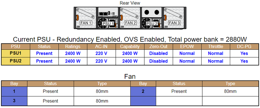
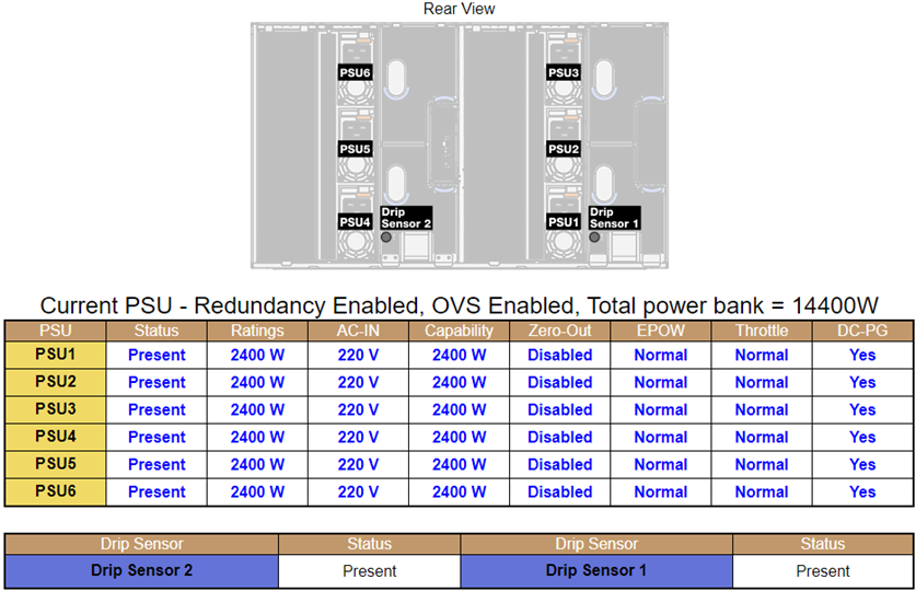
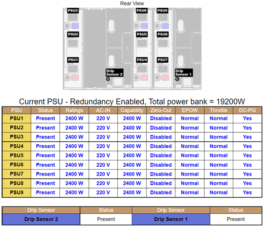
- Status
Present: The power supply is installed.
Not Present: No power supply is installed.
Fault: The power supply is in faulty condition.
Ratings: Power rating, such as 1800 W, 2400 W, 2600 W, and 7200 W, is displayed here. Power rating varies by models, see solution system specifications for details.
AC-IN: AC input power is displayed here.
Capability: The maximum DC output power that the power supply can provide to the entire system is displayed here.
If DC-PG of the power supply is No, capability will be 0 W.
If DC-PG of the power supply is Yes, the capability will be equal to the lower output when power supplies with different wattages are installed in the enclosure at the same time.
Zero-output:
Disabled: Zero-output is disabled.
Wake-Up: Zero-output is enabled. The power supply is in working state.
Sleep: Zero-output is enabled. The power supply is in hibernation with no DC output.
EPOW (Early Power Off Warning)
Assert: The power supply is in input lost condition.
Normal: The power supply AC is working.
Throttle
Assert: The power supply is in over-current condition.
Normal: The power supply is working.
DC-PG (Direct Current - Power Good): The DC power status of the power supply.
No: The power supply is not providing the required DC power.
Yes: The power supply is providing required DC power.
Fan (ThinkSystem DA240 Enclosure only)
Fan: Indicates the status of system fans. This section only applies to DA240 Enclosure.
Status
Present: The fan is installed and in normal operating condition.
Not present: No fan is installed.
Fault: The fan is in faulty condition.
- Type: The system supports 80mm fans.
Drip Sensor (ThinkSystem DW612 and DW612S Neptune DWC Enclosure only)
Drip Sensor: Indicates the status of the drip sensors. This section only applies to DW612 and DW612S Enclosure.
Status
Present: The drip sensor is installed and in normal operating condition.
Not present: No drip sensor is installed.
Fault: The drip sensor is in faulty condition.
The Enclosure Rear View graph is used to illustrate only the locations of the power supply, system fans and drip sensors.
DW612 Enclosure supports three enclosure types. Refer to DW612 Enclosure specifications for more details.
Figure 10. Enclosure Type 1 — DW612 Enclosure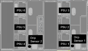 Figure 11. Enclosure Type 2 — DW612 Enclosure
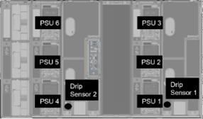 Figure 12. Enclosure Type 3 — DW612 Enclosure
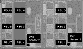
DW612S Enclosure supports five enclosure types. Refer to DW612S mechanical specifications for more details.
Figure 13. Enclosure Type 1 — DW612S Enclosure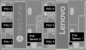 Figure 14. Enclosure Type 2 — DW612S Enclosure
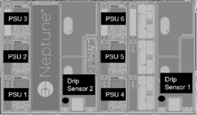 Figure 15. Enclosure Type 3 — DW612S Enclosure
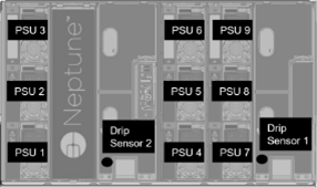 Figure 16. Enclosure Type 5 — DW612S Enclosure
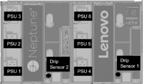 Figure 17. Enclosure Type 6 — DW612S Enclosure
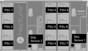
- 2600W PSUs will be derated to 2400W under AC high low line; 7200W PSUs will be derated to 6900W under AC high low line.