Install a 7mm NVMe drive
Use this information to install a 7mm NVMe drive.
About this task
Required tools
Make sure you have the required tools listed below in hand to properly replace the component.
Read Installation Guidelines and Safety inspection checklist to ensure that you work safely.
For gap pad location and instruction, see Gap pad identification and location.
Before replacing the gap pad, gently clean the surface with an alcohol cleaning pad.
Hold the gap pad carefully to avoid deformation. Make sure no screw hole or opening is blocked by the gap pad material.
- A video of this procedure is available at YouTube.
Procedure
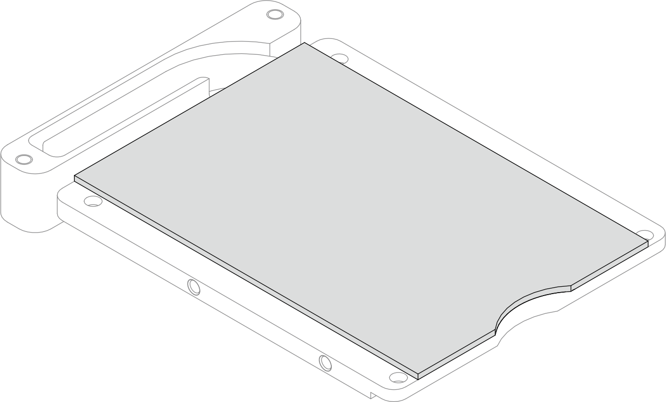
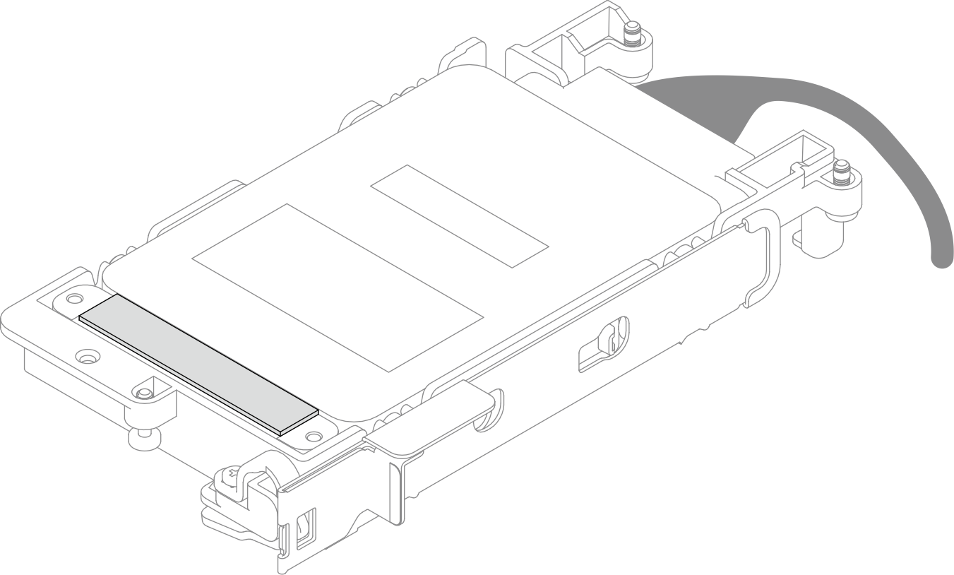
- If the gap pad on the conduction plate is damaged or detached, discard the conduction plate. Then, install a new conduction plate already attached with the gap pad.Figure 1. Conduction plate gap pad installation
- Install the conduction plate to the drive cage.
 Unlock the metal tab on the drive cage.
 Align the conduction plate to two guide pins on the drive cage; then, install the conduction plate to the drive cage as shown.
 Install the four screws to secure the conduction plate to the drive cage.
Figure 2. Conduction plate installation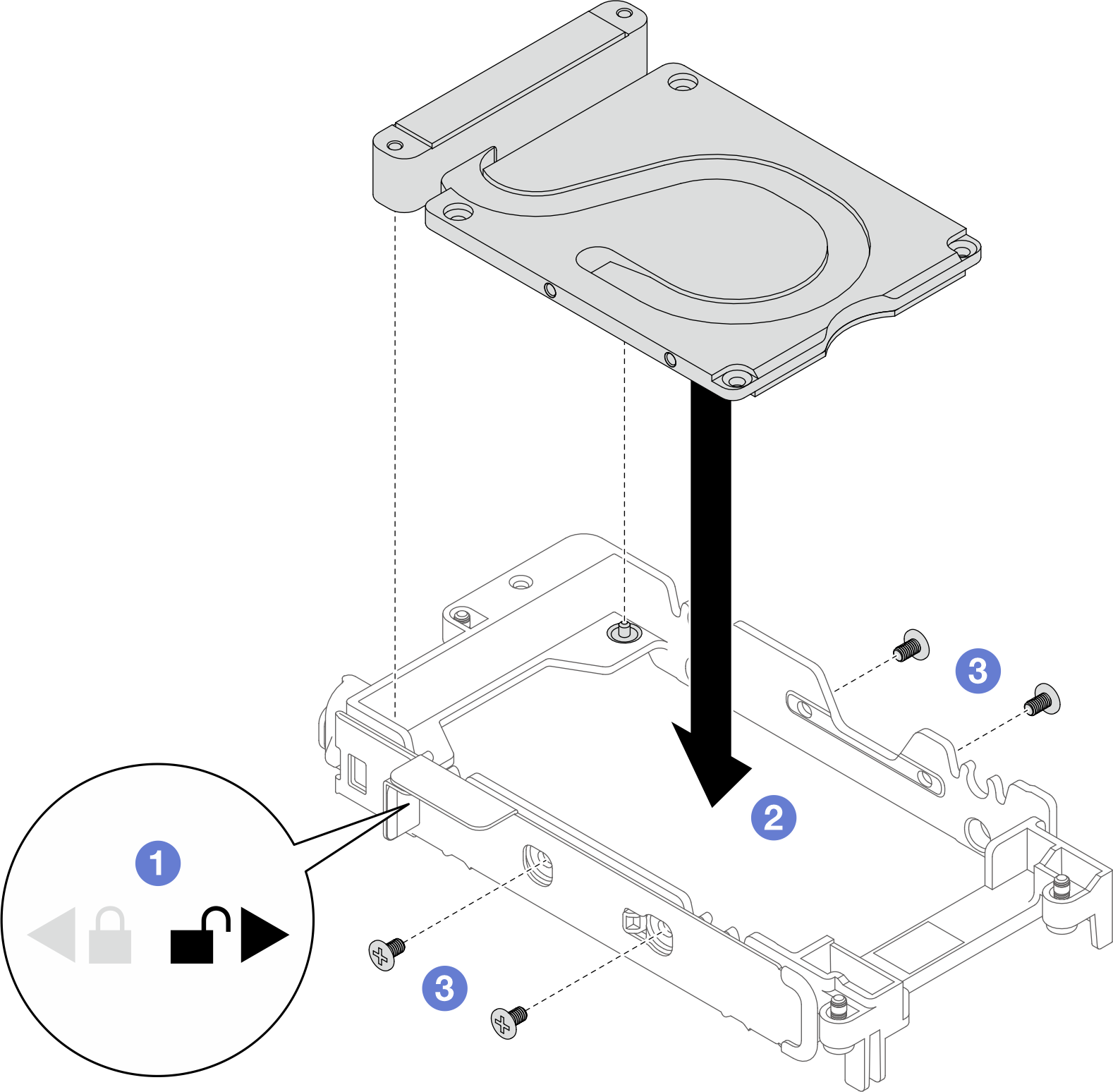
- Install the lower drive.
- Connect the cable with SSD 0/2 marked on plugger to the drive.
- Install the drive into the bottom of the drive cage and make sure it is secured in place.
Figure 3. Lower drive installation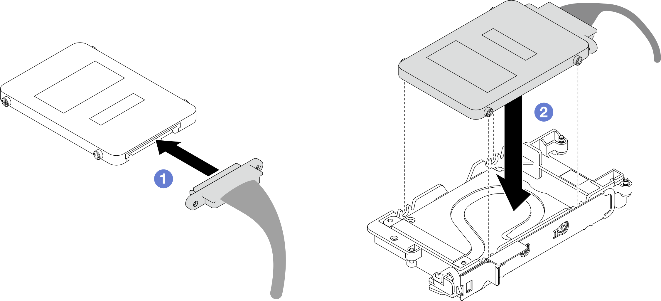
- Install the upper drive.
- Connect the cable with SSD 1/3 marked on plugger to the drive. Then, insert the screws on the drive into the two screw holes on the drive cage.
- Rotate the drive into the drive cage.
- Press the drive into the drive cage.
 While pressing down the drive, push and hold the release latch.
 Slide the metal tab to the lock position.
Figure 4. Upper drive installation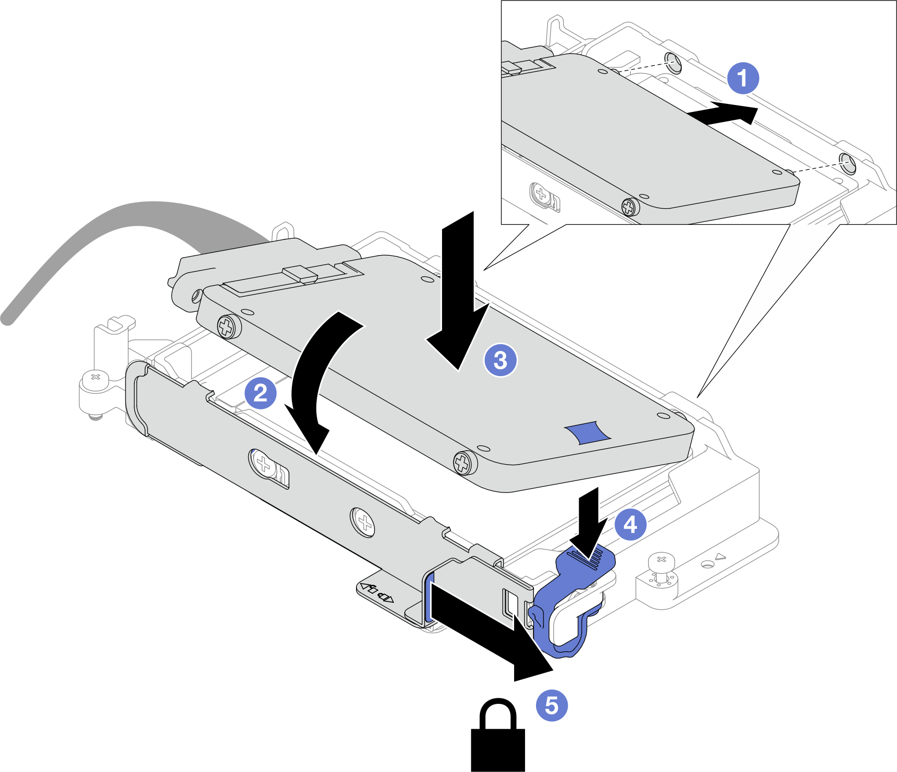
- Replace the putty pad on the conduction plate. Make sure to follow Gap pad/putty pad replacement guidelines.
Install the cross braces. See Install the cross braces.
Install the tray cover. See Install the tray cover.
Install the tray into the enclosure. See Install a tray in the enclosure.
- Connect all required external cables to the solution.NoteUse extra force to connect QSFP cables to the solution.
- Check the power LED on each node to make sure it changes from fast blink to slow blink to indicate all nodes are ready to be powered on.Note
Shared I/O configuration requires specific nodes power-on sequence. When powering on the system, power on Node B first; then, power on Node A. For more information, see PCIe adapter cable routing.