Install a tray in the enclosure
Use this information to install a DWC tray in the enclosure.
About this task
Read Installation Guidelines and Safety inspection checklist to ensure that you work safely.
The following illustration might differ slightly from your hardware, but the installation method is the same.
Make sure the SMM3 firmware version is Q4SM08E or later version.
Lift tool assembly
Genie GL-8 lift tool installed with the lift tool fixture. The foot-release brake should also be attached to the lift tool.
For assembling instructions, see Setting up the lift tool assembly
Rotate fixture cart assembly
Rotate fixture installed on the customized cart.
For assembling instructions, see Setting up the rotate fixture cart assembly
For mandatory tools ordering information, see ThinkSystem server options.
- A video of this procedure is available at YouTube.
Procedure
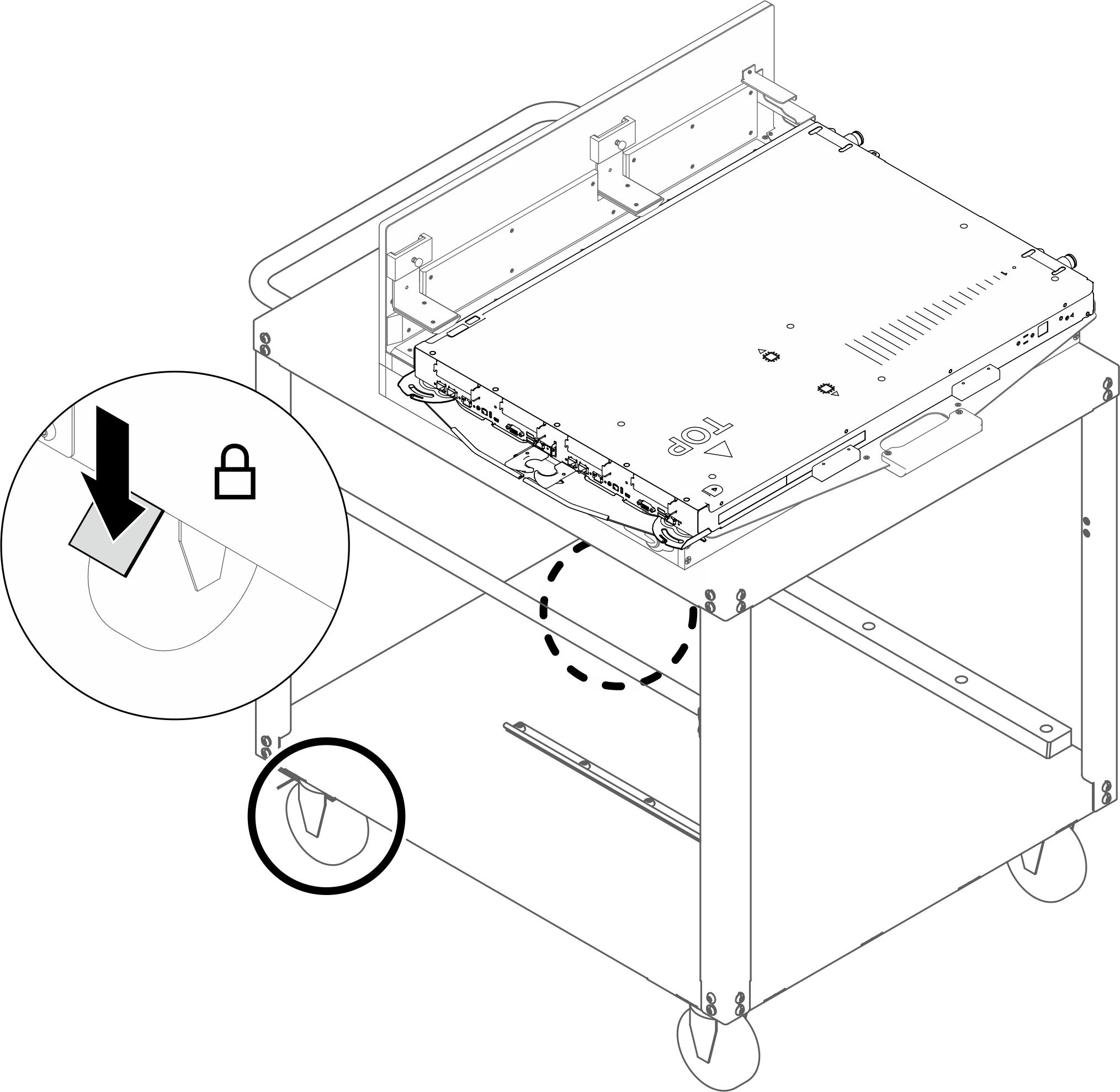
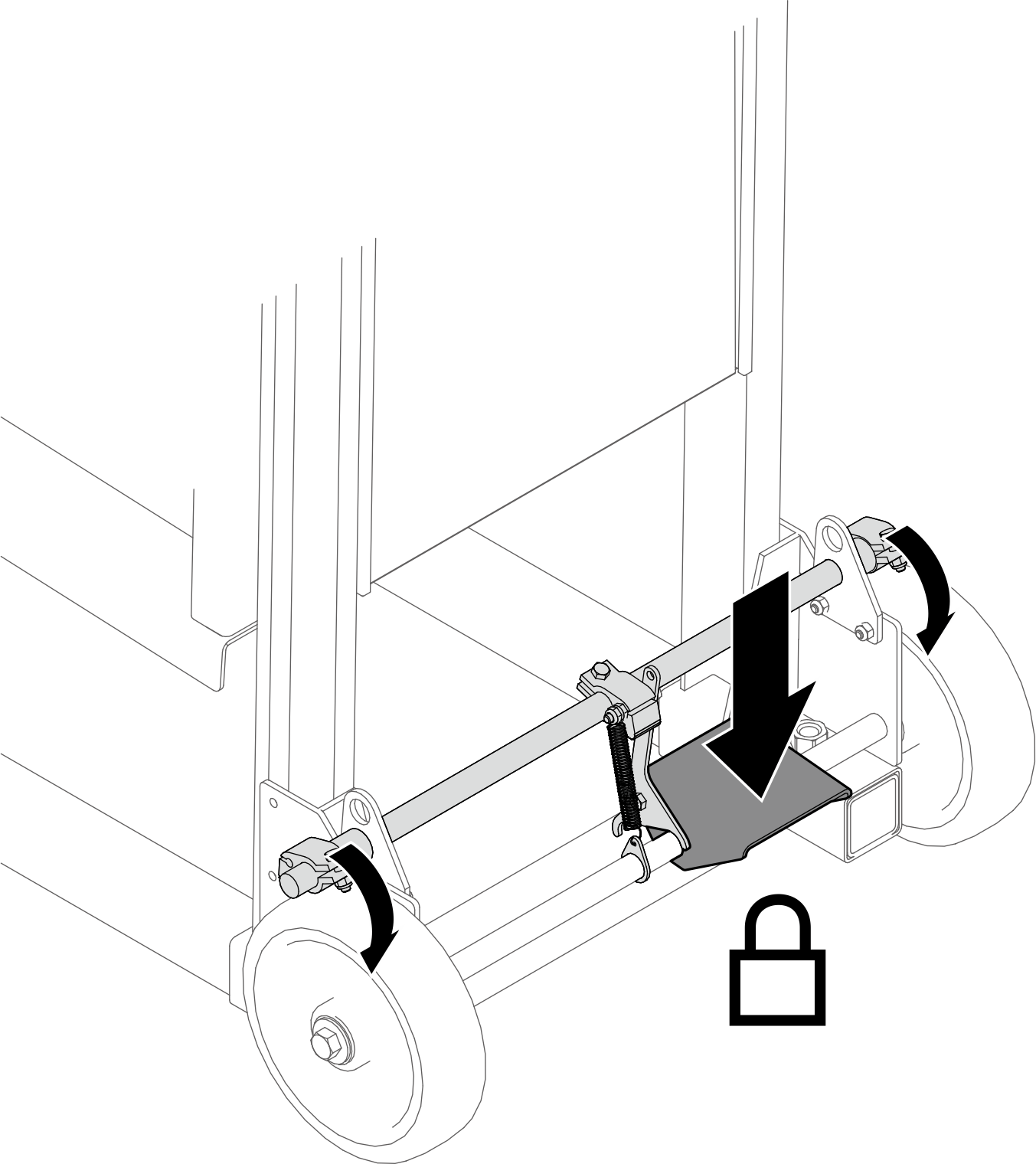
- Push down the foot pedal to lock the wheel brakes on the rotate fixture cart.Figure 2. Locking the cart wheel brakes
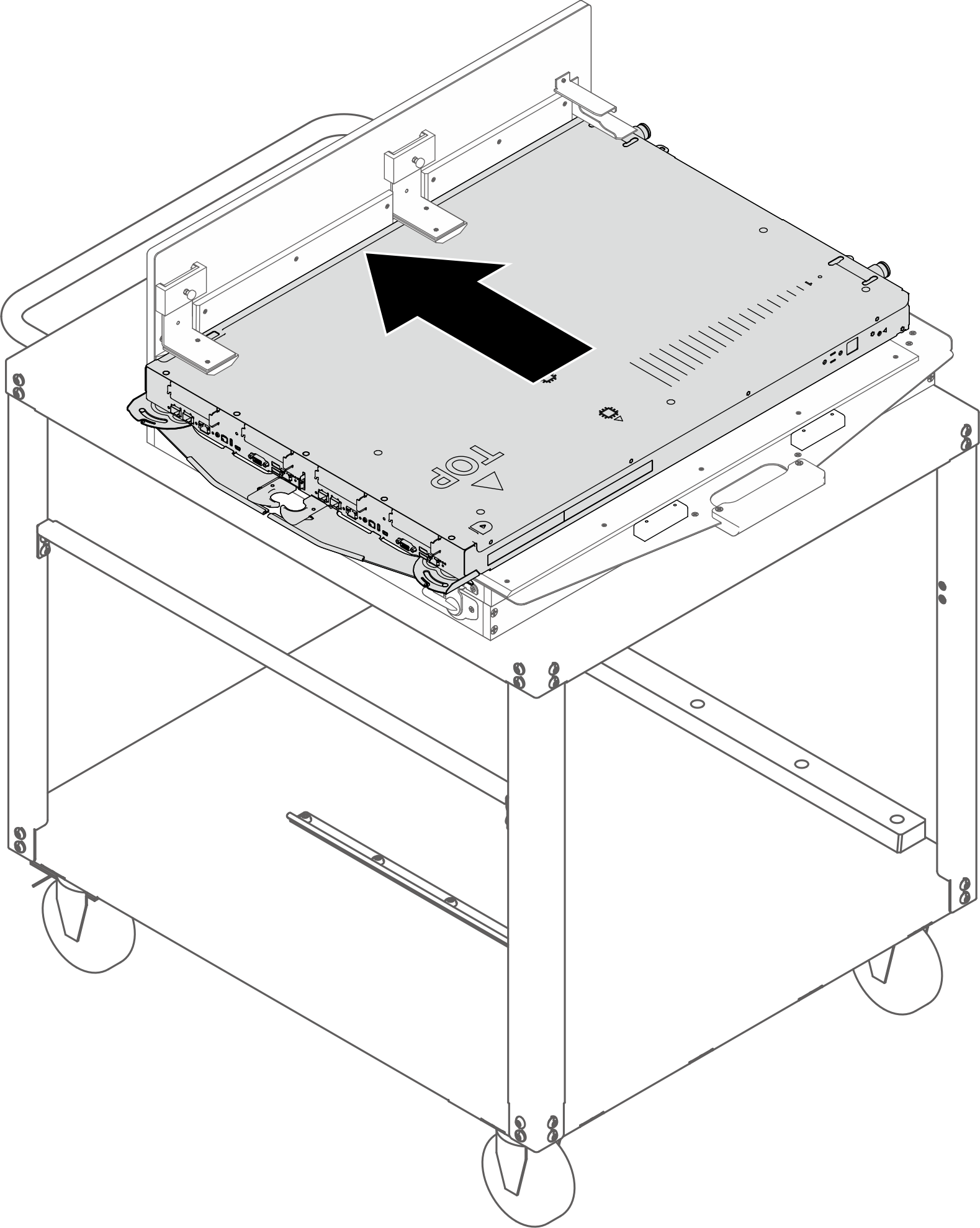
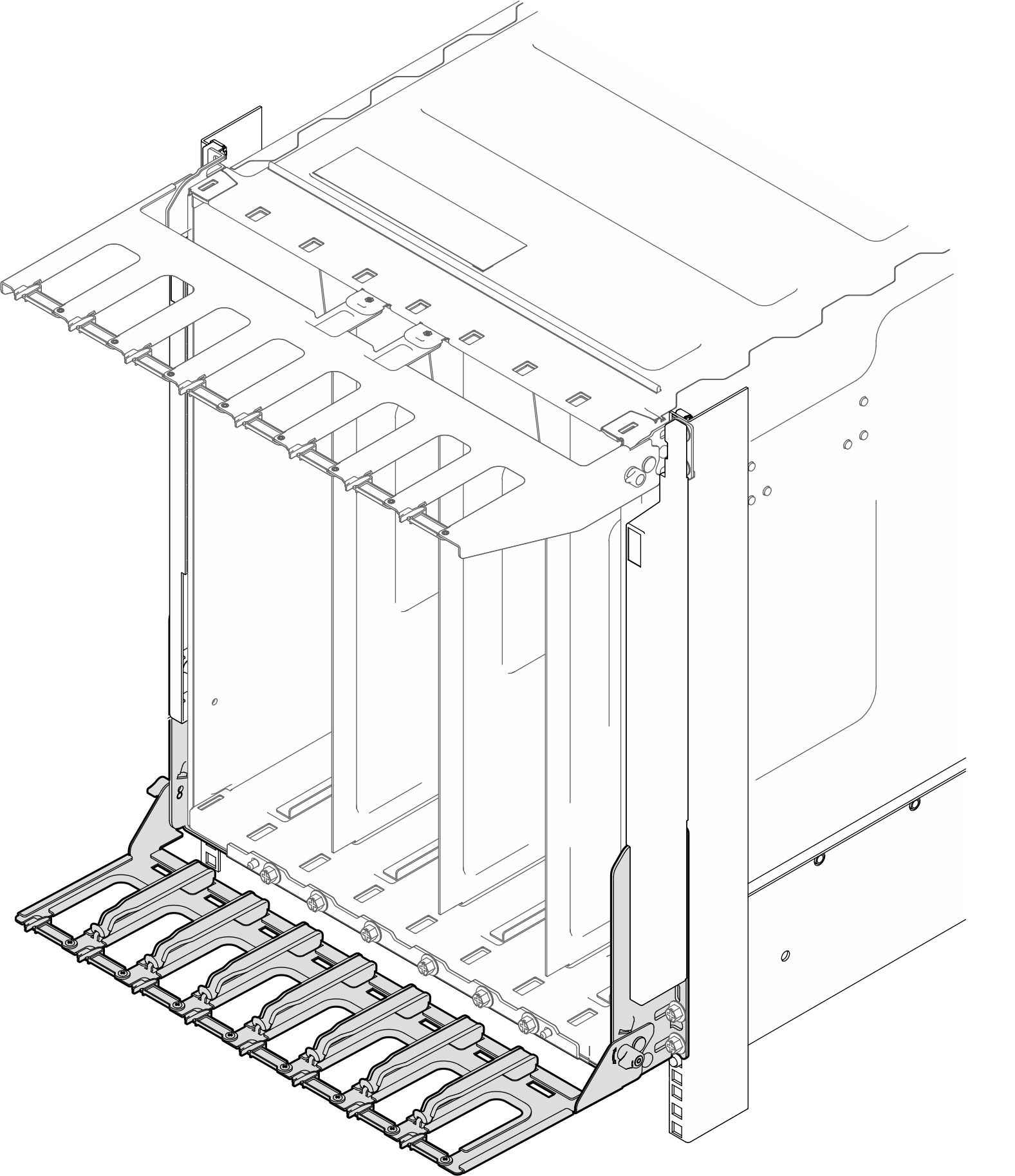
- Push the tray into the angle brackets.Figure 3. Pushing tray into angle brackets
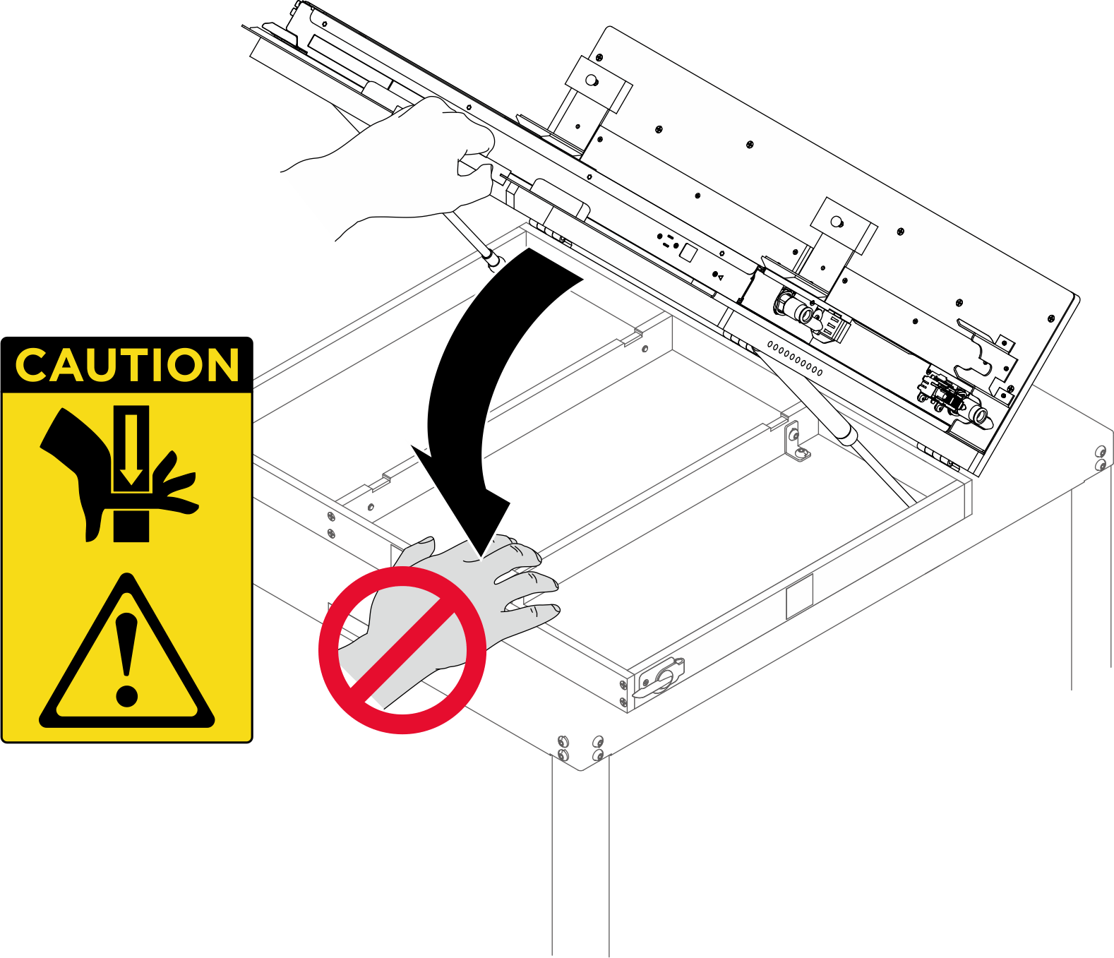
- Open the rotate fixture.
 Grab the handle, and hold the handle down with extra force.Figure 4. Holding down the fixture handle
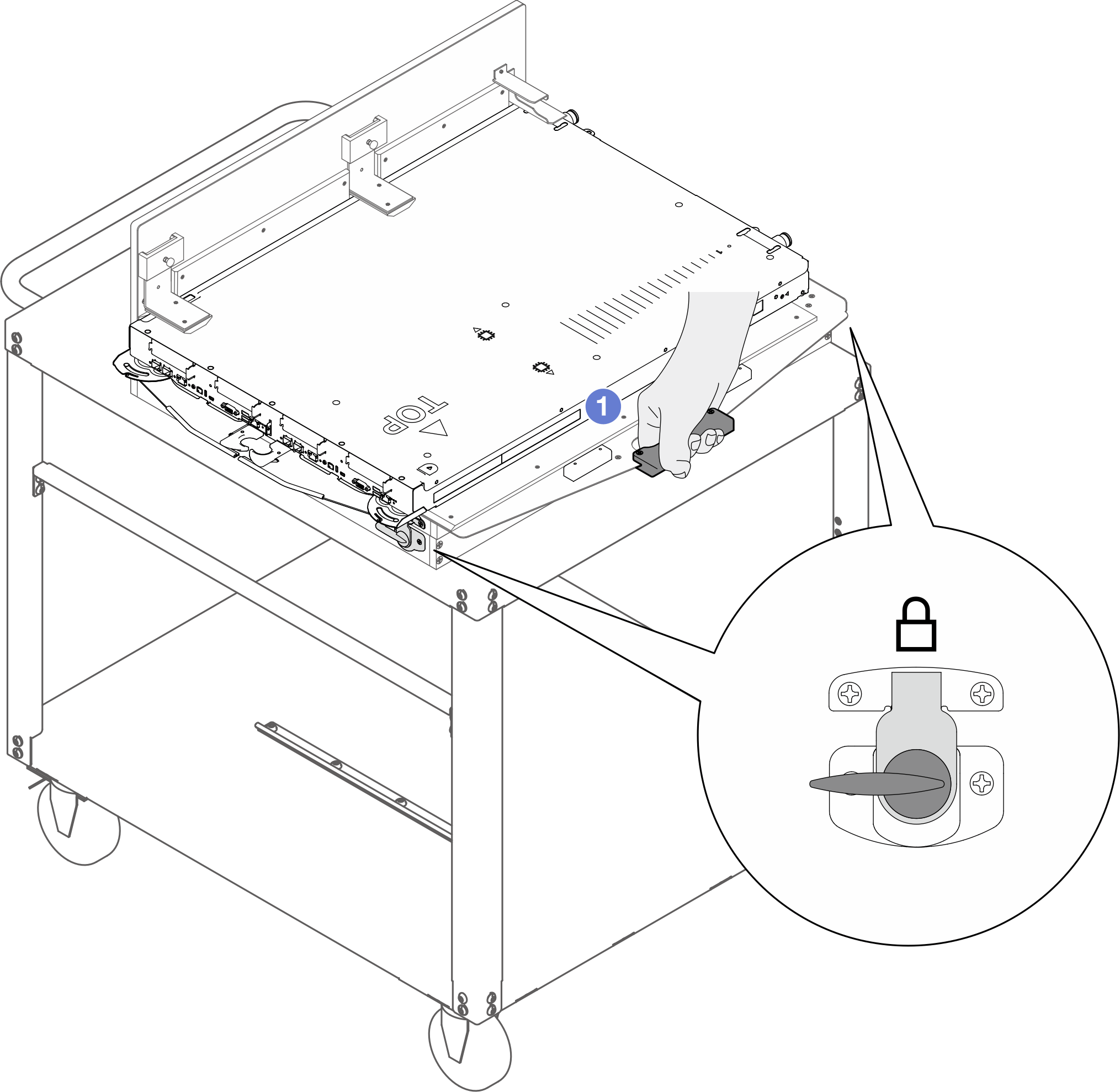
 Keep holding down the handle. Meanwhile, rotate the latch counterclockwise until it is unlocked. Make sure to unlock the latches on the right and left sides of the fixture.Figure 5. Locking the rotate fixture latches
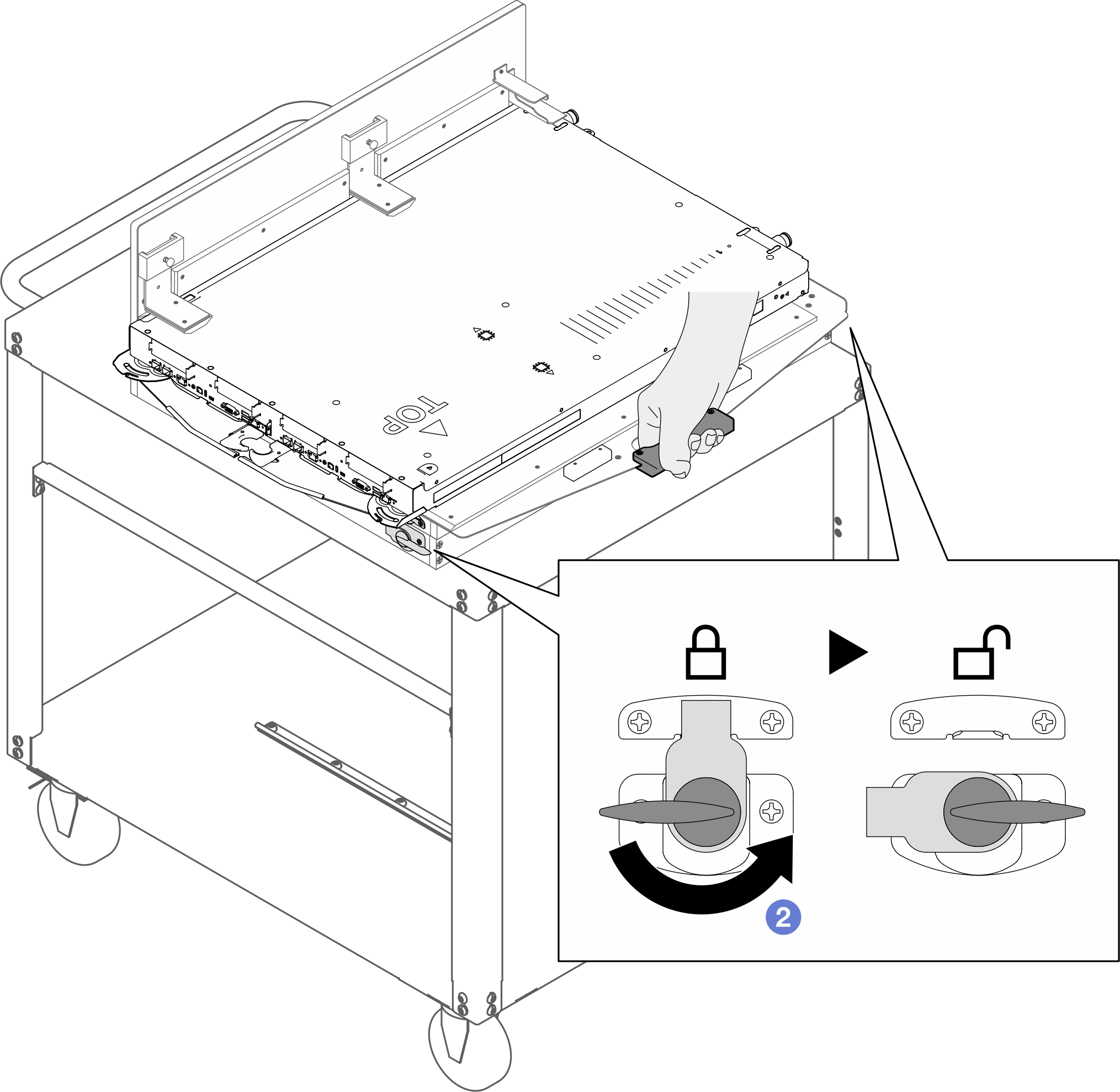
 Hold the handle; then, slowly rotate it upward until it stands vertically.AttentionMake sure you are holding the handle while opening the rotate fixture.Figure 6. Opening the rotate fixture
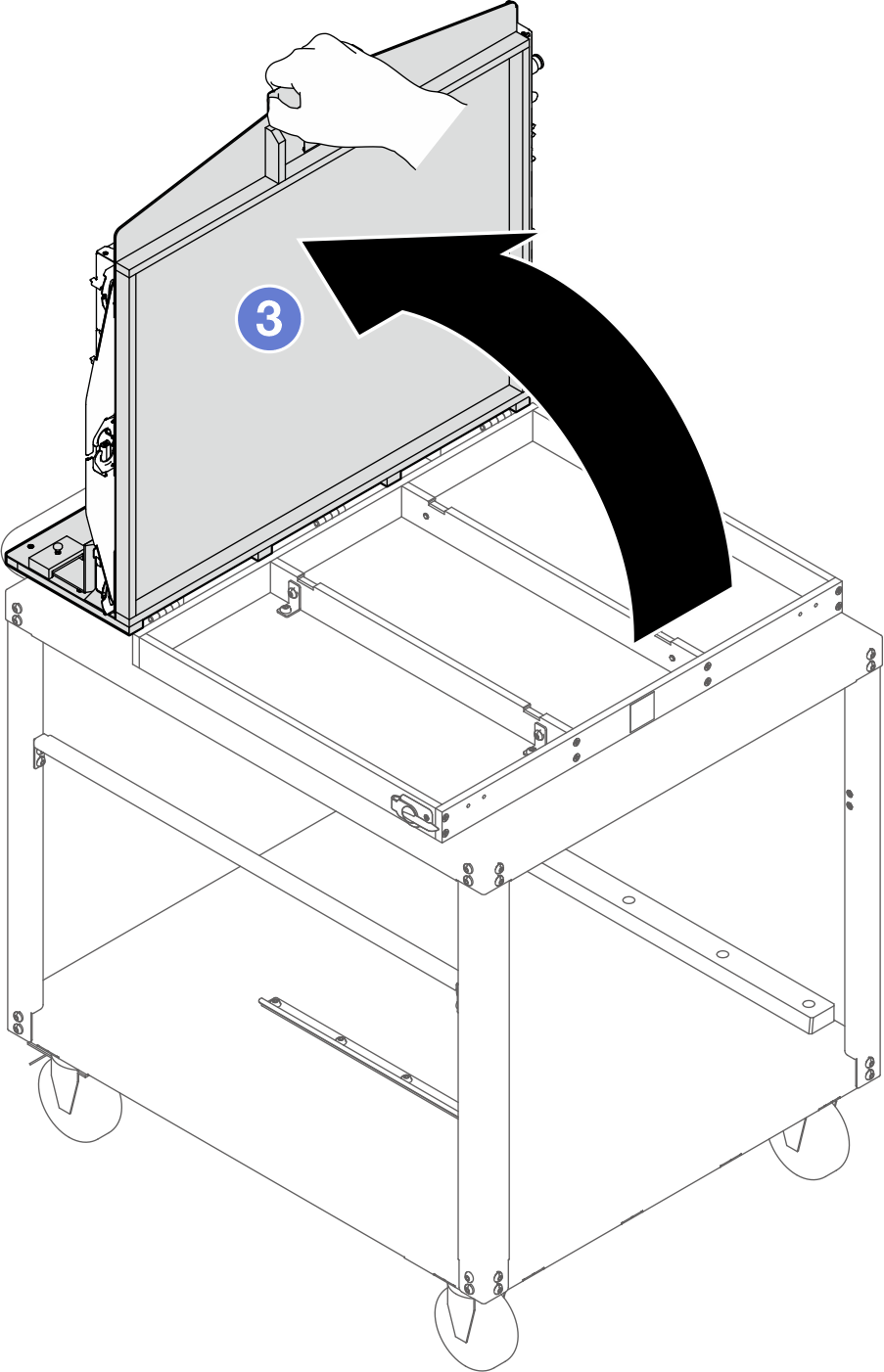
- Adjust the fixture guide fence to the SW position (Single Wide). If the guide fence is not in SW position, lift the guide fence, and re-install it to the SW slots.
Fence label description Full description SW Single Wide PCS Power Conversion Station DW Double Wide Figure 7. Fixture guide fence set to SW position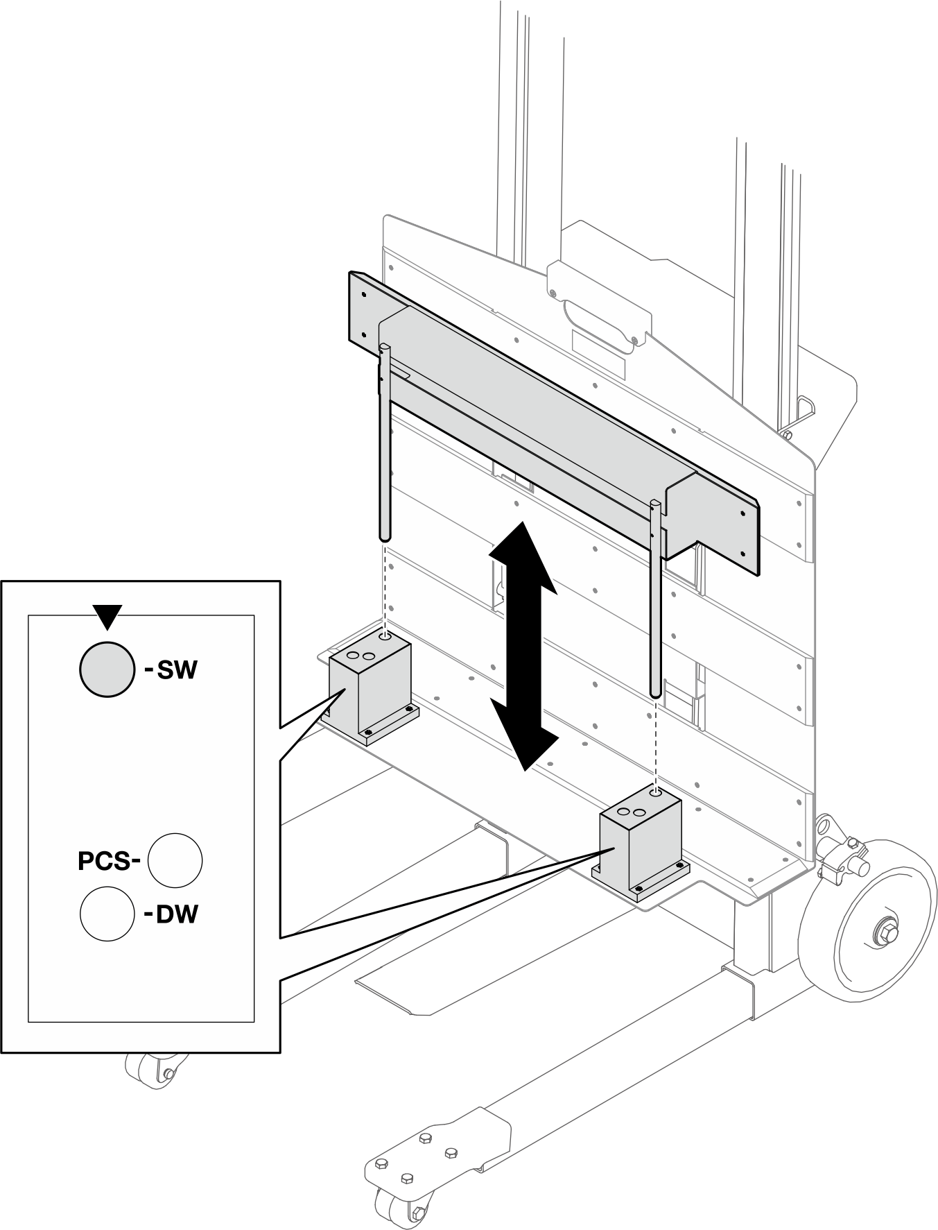
- Move the lift tool assembly next to the rotate fixture cart assembly as shown in the illustration below. Adjust the lift tool so that the lift tool fixture bottom aligns with the rotate fixture bottom, and the sides of both fixtures are in parallel.NoteRotate the lift tool handle
clockwise to raise the fixture; counterclockwise to lower the fixture. 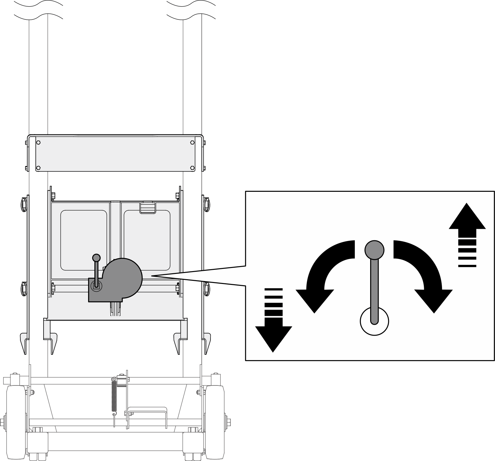 Figure 8. Aligning lift tool fixture and rotate fixture bottoms and sides
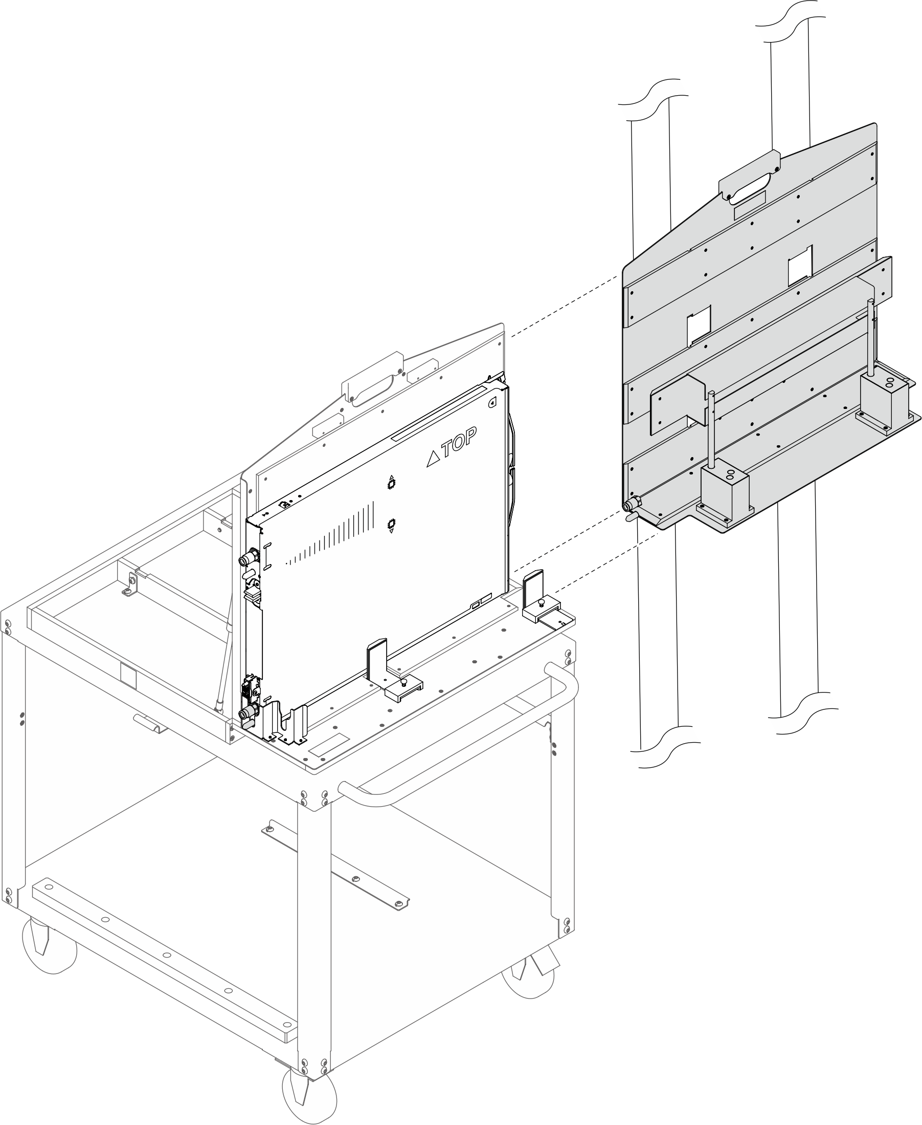
- Push down the foot pedal to lock the wheel brake of the lift tool.Figure 9. Locking the lift tool wheel brake
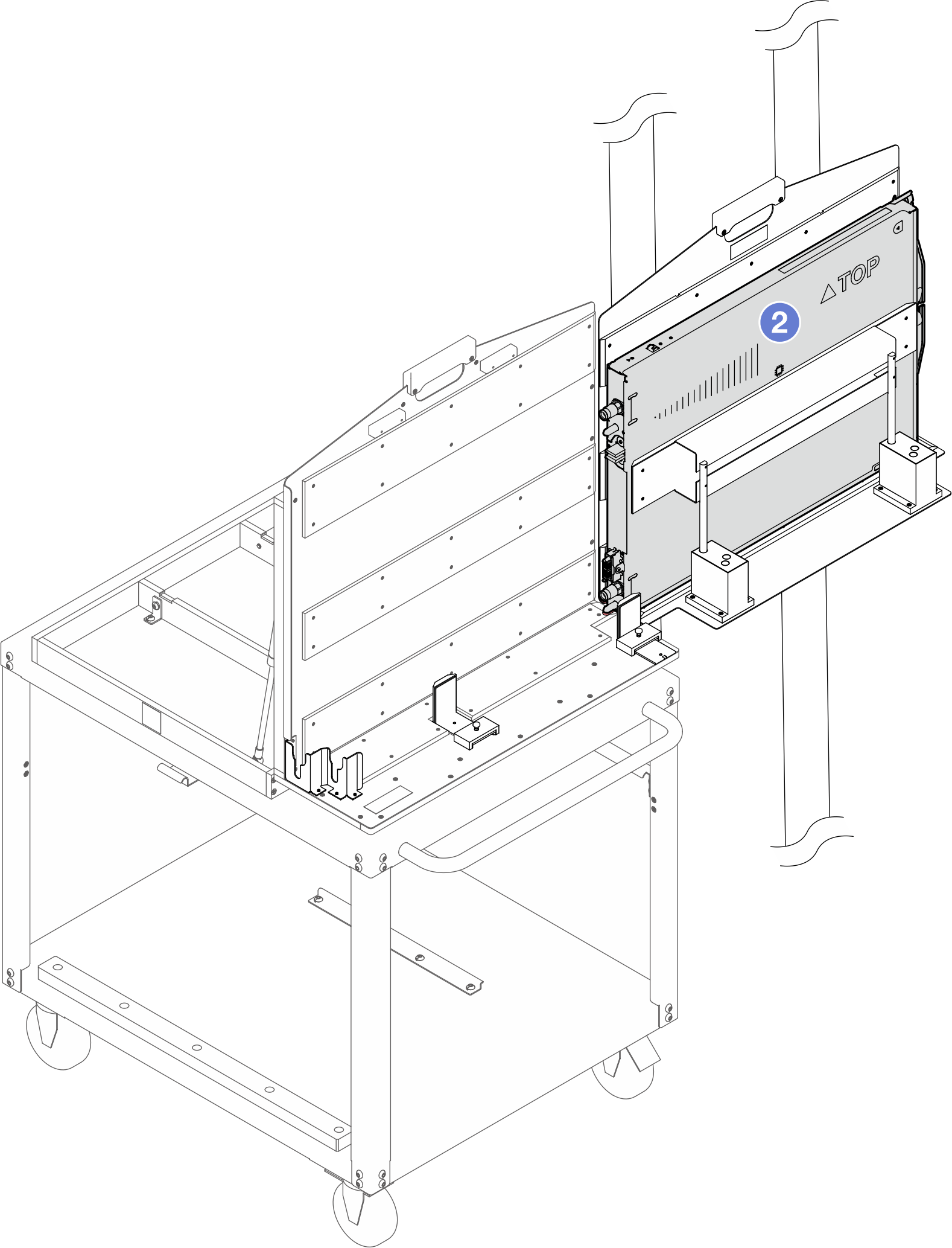
- Transfer the tray to the lift tool fixture.
- Slide the tray to the lift tool fixture until it is partially seated in the lift tool fixture.
- Slide the tray all the way into the lift tool fixture until the tray is completely seated in the lift tool fixture.
Figure 10. Transferring the tray to the lift tool fixture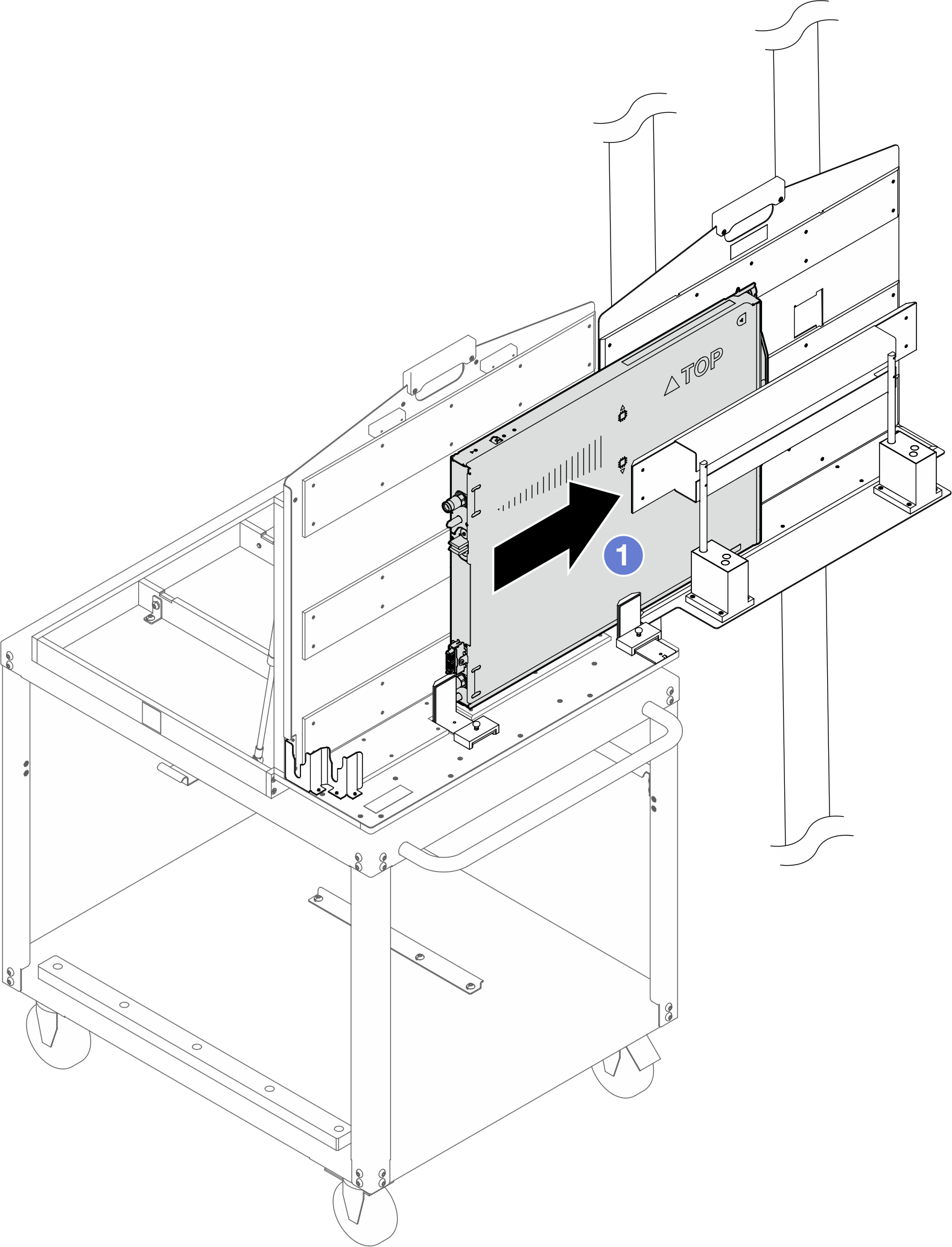
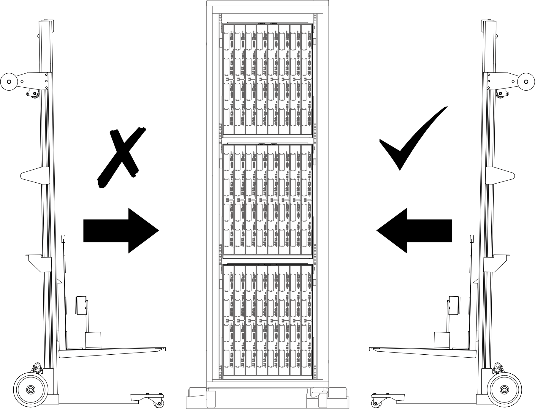
- Move the lift tool assembly to the front of the rack. Make sure the fixture front side is facing the tray back side.Figure 11. Lift tool assembly placement in front of the rack
- Adjust the lift tool so that the tray aligns with the tray bay in the enclosure.NoteRotate the lift tool handle
clockwise to raise the fixture; counterclockwise to lower the fixture. Figure 12. Aligning fixture and the tray bottoms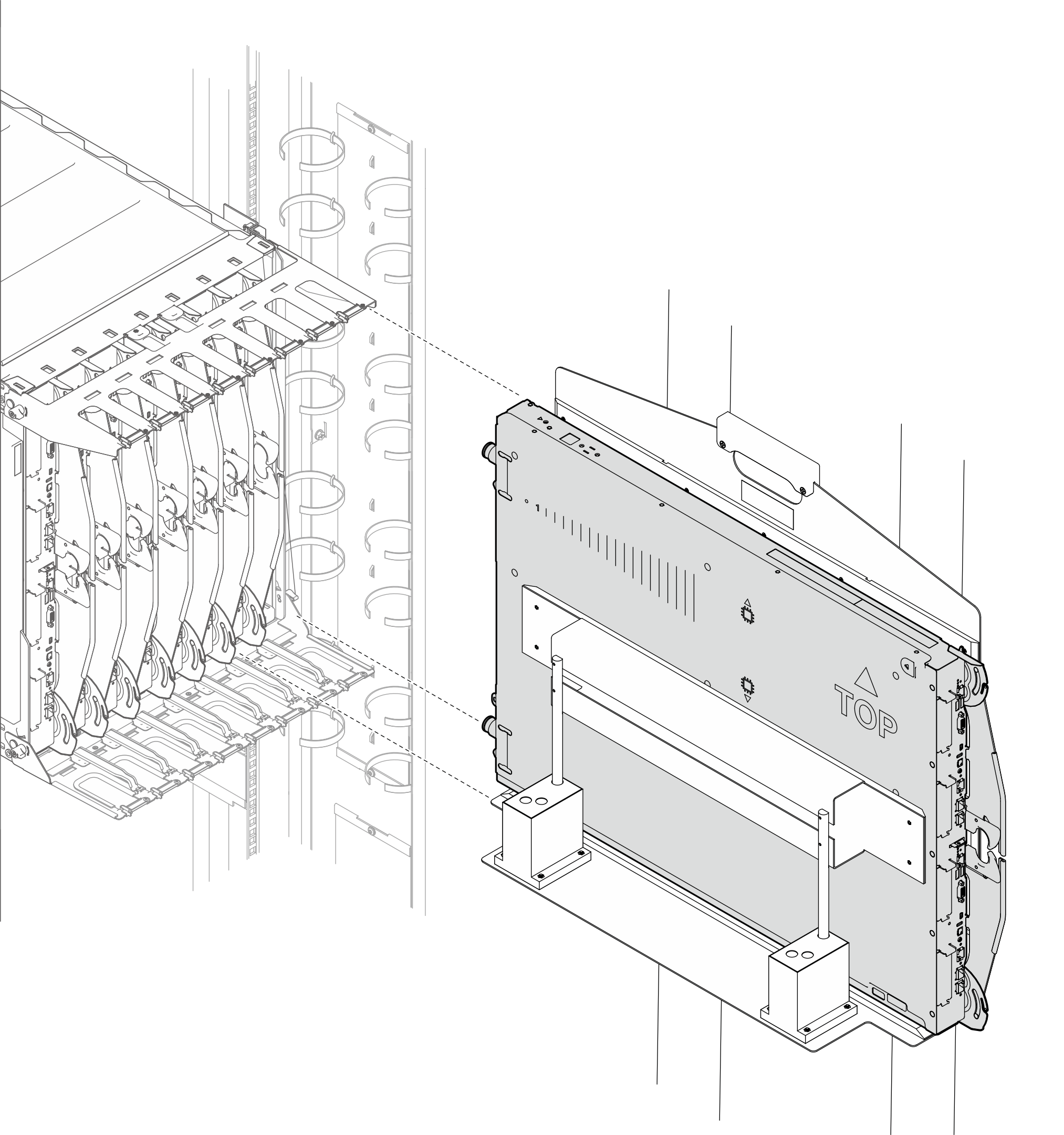 Figure 13. Aligning fixture front side with tray back side
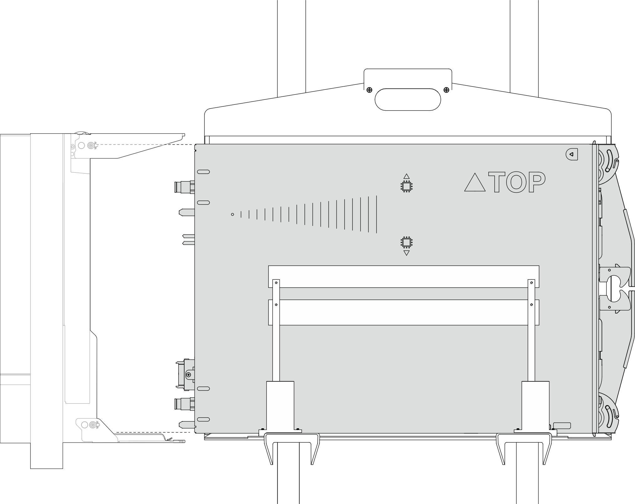
- Transfer the tray to the tray bay in the enclosure.
- Grab the top and bottom parts of the tray.
- Slide the tray into the tray bay until only the TOP printing is seen.
Figure 14. Slising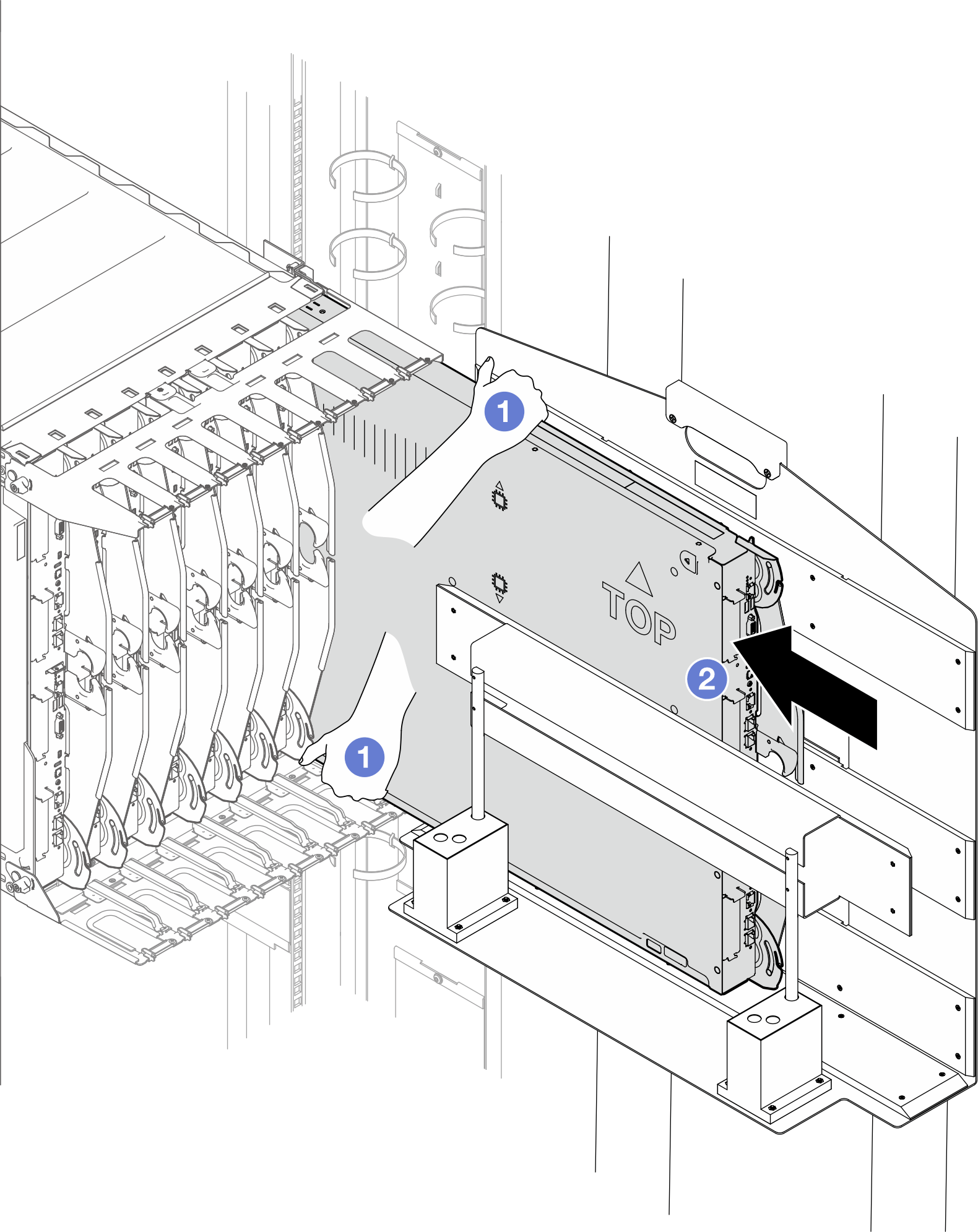
- Place the tray into the enclosure.
- Rotate the tray handles to the open position.
- Insert the tray into the tray bay in the enclosure.
Figure 15. Placing the tray into the enclosure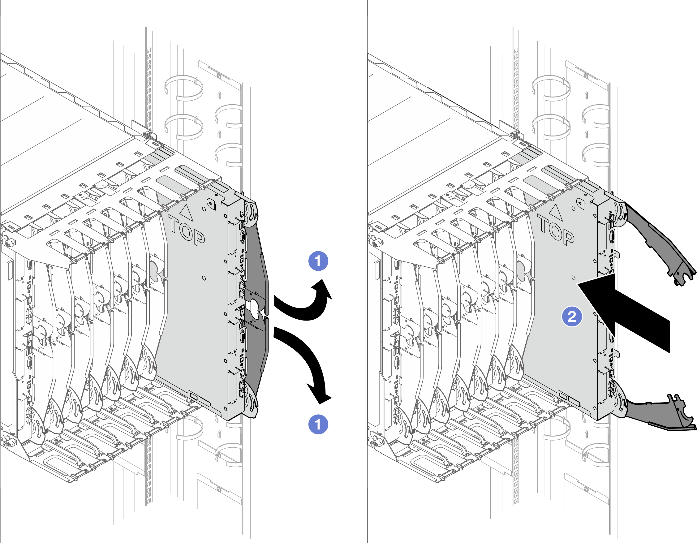
- Insert the tray into the tray bay while tray handles are in the open position.
- Rotate the tray handles to the open position.
- Push the tray into the enclosure until the handles bump into the enclosure edges.
Figure 16. Pushing the tray into the enclosure until handles bump into enclosure edges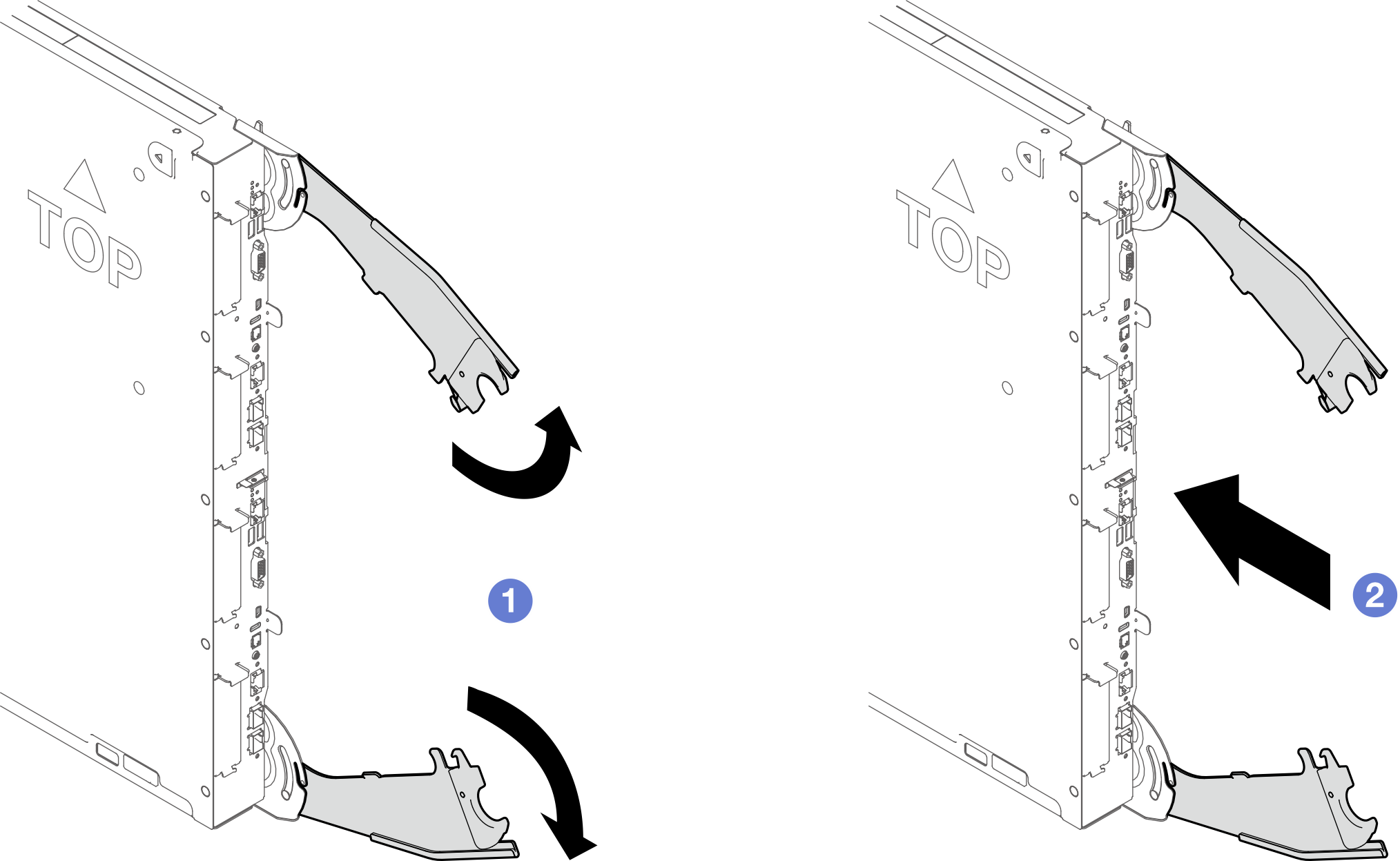
- Push the tray into the enclosure until the tip of the tray handle touches the enclosure. Make sure there is no distance between the enclosure and the tip of the handle.Figure 17. Checking tray handle position
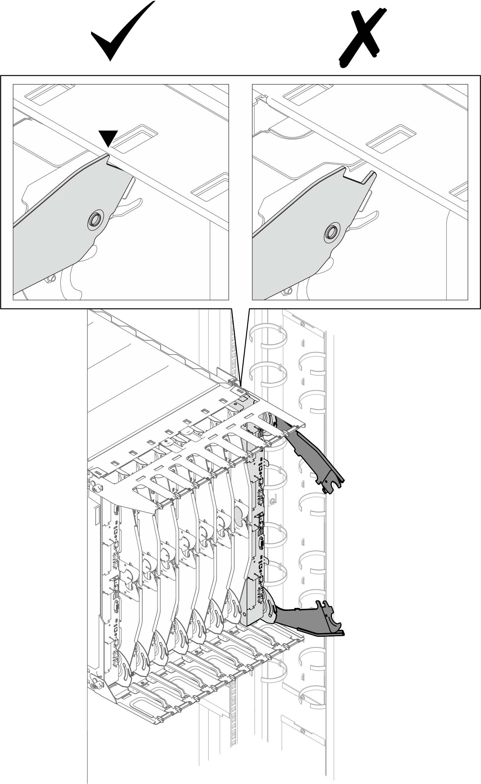 Figure 18. Distinguishing correct tray handle position
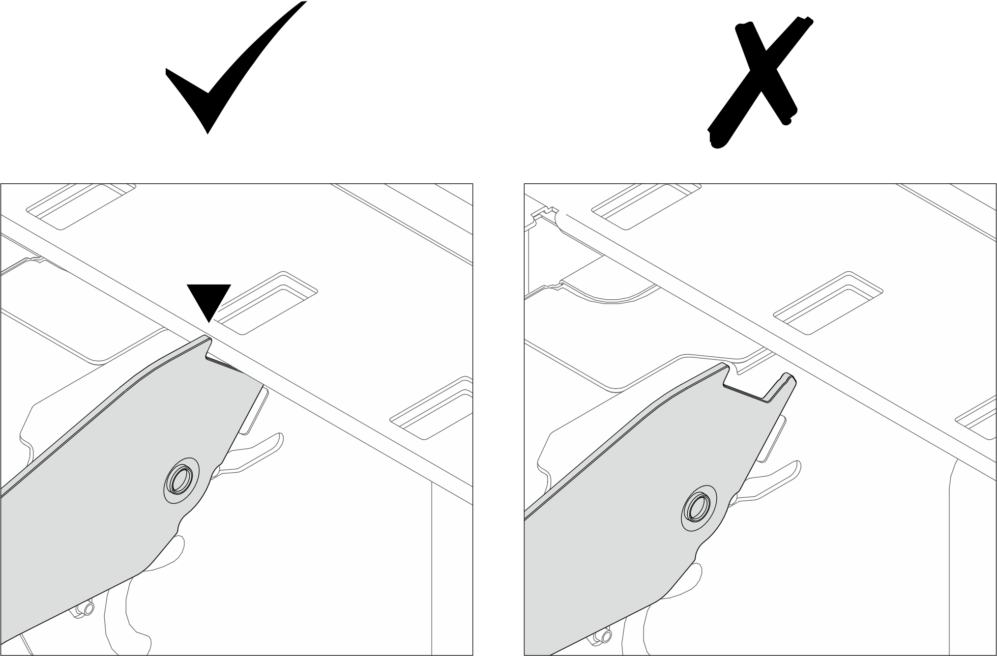
- Rotate the bottom handle for 45 degrees to push the tray slightly into the enclosure. DO NOT rotate the bottom handle all the way in.NoteIf the tray does
not move into the enclosure as you rotate the bottom handle, the handles are not in correct position. Reinstall the tray until the handles are seated correctly and handle rotation can bring about tray movement. Figure 19. Slightly rotating bottom tray handle to move the tray forward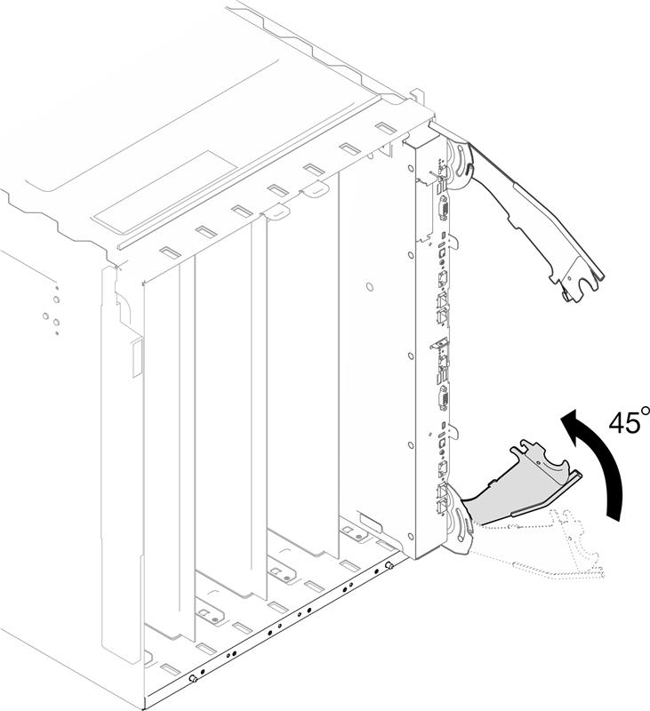
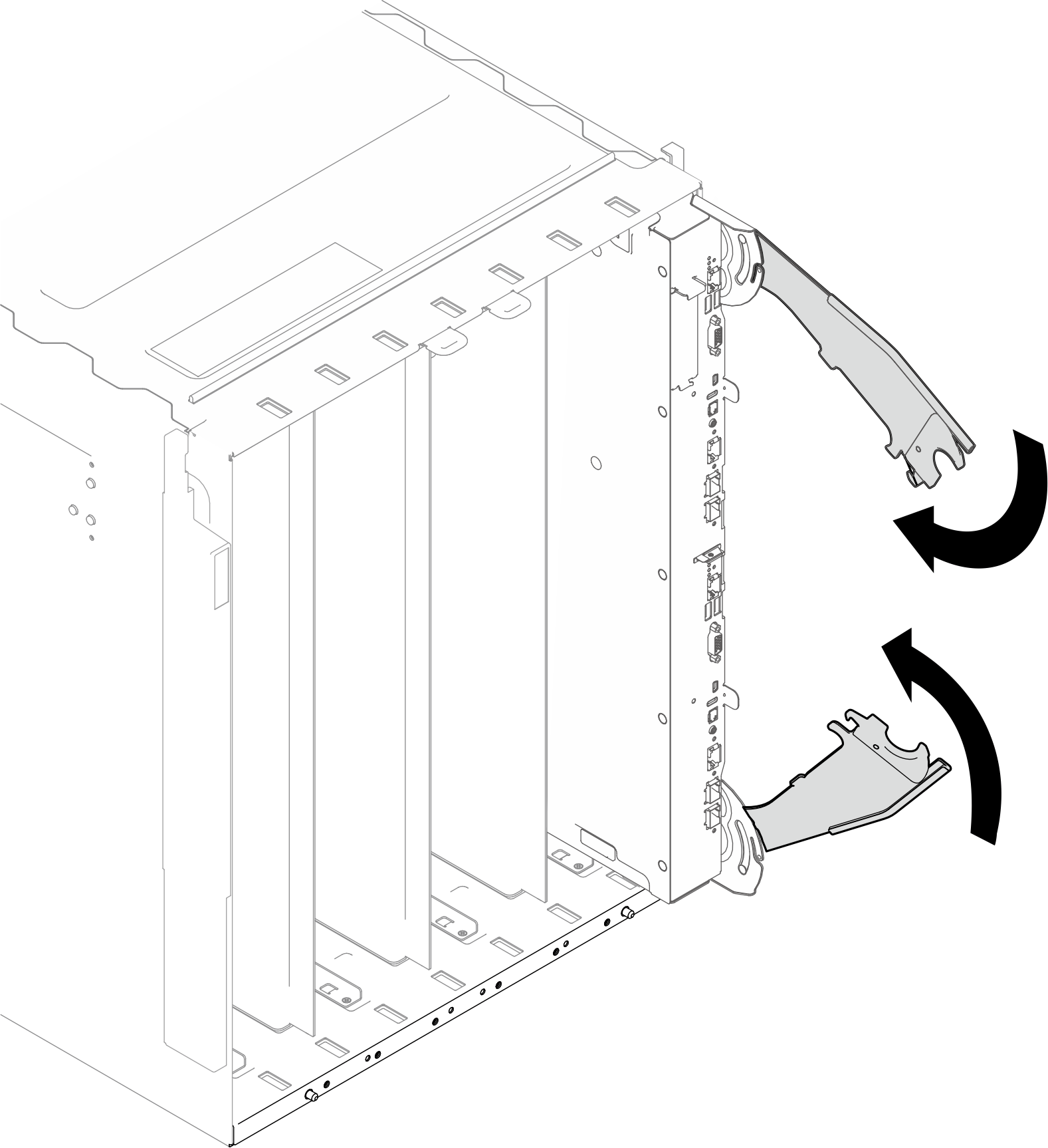
- Rotate both top and bottom handles to the closed position to secure the tray in the enclosure.Figure 20. Rotating both tray handles to the closed position
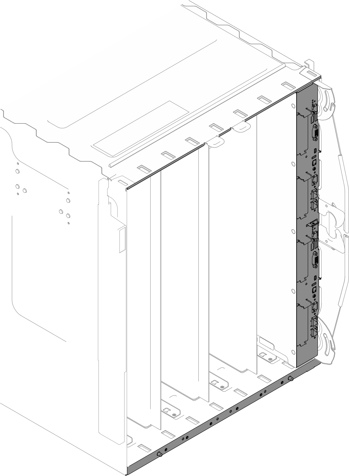
- Make sure the tray does not protrude from the enclosure. The surface of the tray front bezel and the enclosure outer frame should be aligned as a flat surface.Figure 21. Tray front bezel and enclosure outer frame surface alignment
After you finish
If this is the initial installation of the DWC tray in the enclosure, you must configure the DWC tray through the Setup Utility and install the DWC tray operating system.
If you have changed the configuration of the DWC tray or if you are installing a different DWC tray from the one that you removed, you must configure the DWC tray through the Setup Utility, and you might have to install the DWC tray operating system.
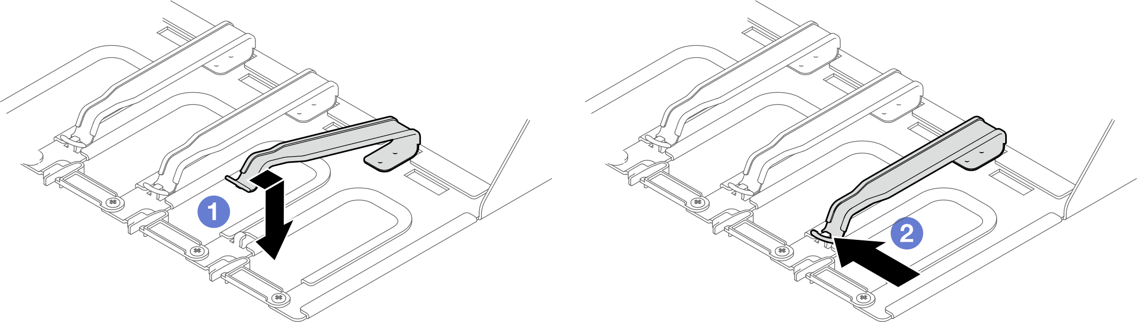
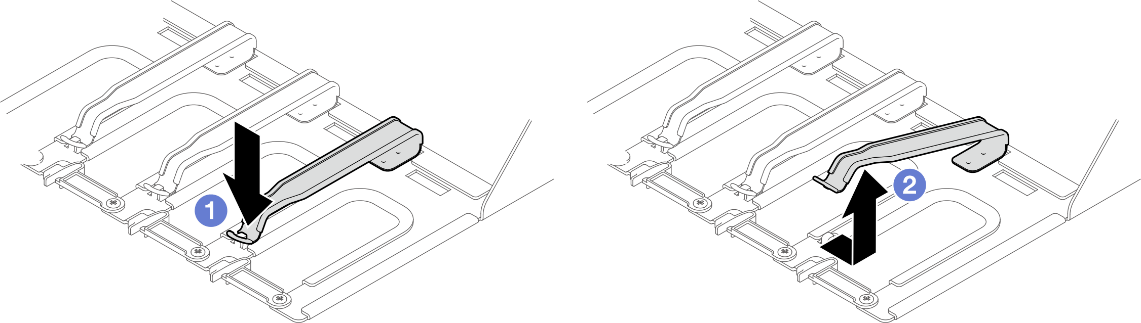
Opening the cable retainer
- Press down the cable retainer.
- Pull the cable retainer to the right; then, pull it up.
Closing the cable retainer
- Pull the cable retainer to the right; then, press it down.
- Pull the cable retainer to the left to secure it to the support bracket.