Remove a tray from the enclosure
Use this information to remove a DWC tray from the enclosure.
About this task
Lift tool assembly
Genie GL-8 lift tool installed with the lift tool fixture. The foot-release brake should also be attached to the lift tool.
For assembling instructions, see Setting up the lift tool assembly
Rotate fixture cart assembly
Rotate fixture installed on the customized cart.
For assembling instructions, see Setting up the rotate fixture cart assembly
For mandatory tools ordering information, see ThinkSystem server options.

Read Installation Guidelines and Safety inspection checklist to ensure that you work safely.
Turn off the corresponding DWC tray that you are going to perform the task on.
Disconnect all external cables from the enclosure.
Use extra force to disconnect QSFP cables if they are connected to the solution.
The following illustration might differ slightly from your hardware, but the removal method is the same.
Opening the cable retainer
 Press down the cable retainer.
 Pull the cable retainer to the right; then, pull it up.
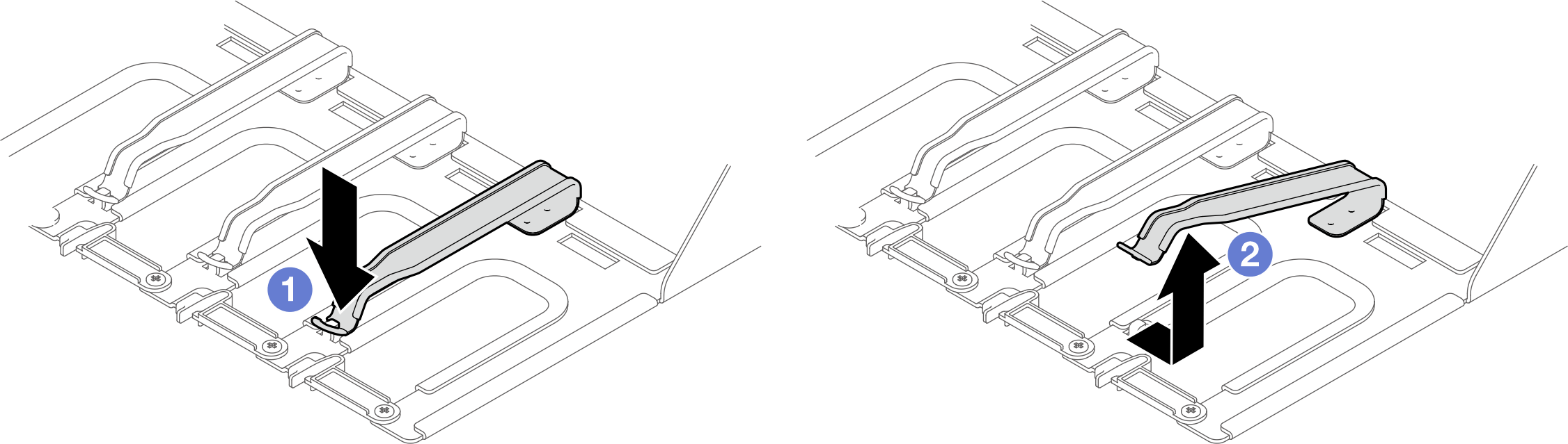
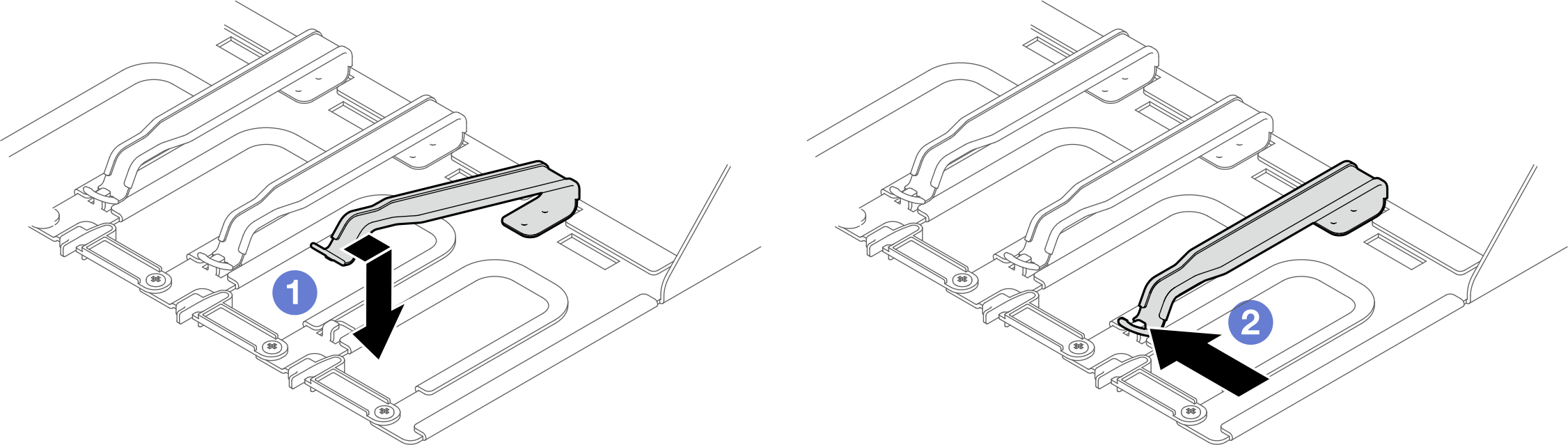
Closing the cable retainer
- Pull the cable retainer to the right; then, press it down.
- Pull the cable retainer to the left to secure it to the support bracket.
- A video of this procedure is available at YouTube.
Procedure
The tray might be very hot. Wait several minutes to let the tray cool before removing the tray cover.
- Remove the tray from the enclosure.
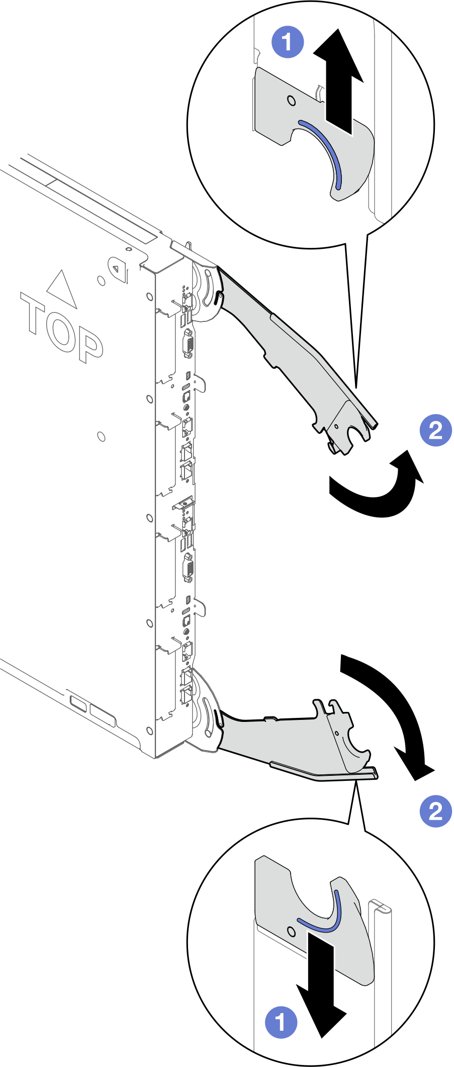
- Press the latches on the front cam handles.
- Rotate the front cam handles as shown in the illustration. The tray moves out of the tray bay approximately 2 cm (0.78 inch).Figure 3. Opening the tray cam handles
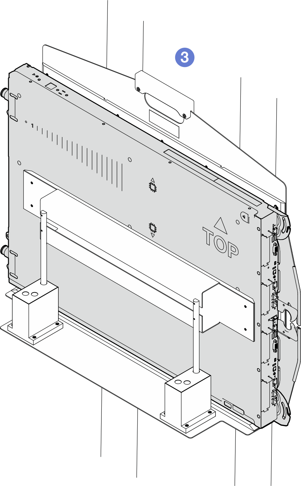
 Grab the cam handles and pull the DWC tray slightly out of the enclosure.
 Pull the tray out until you see the TOP printing on the top cover. Then, close the cam handles.Figure 4. Pulling the tray slightly out of the enclosure
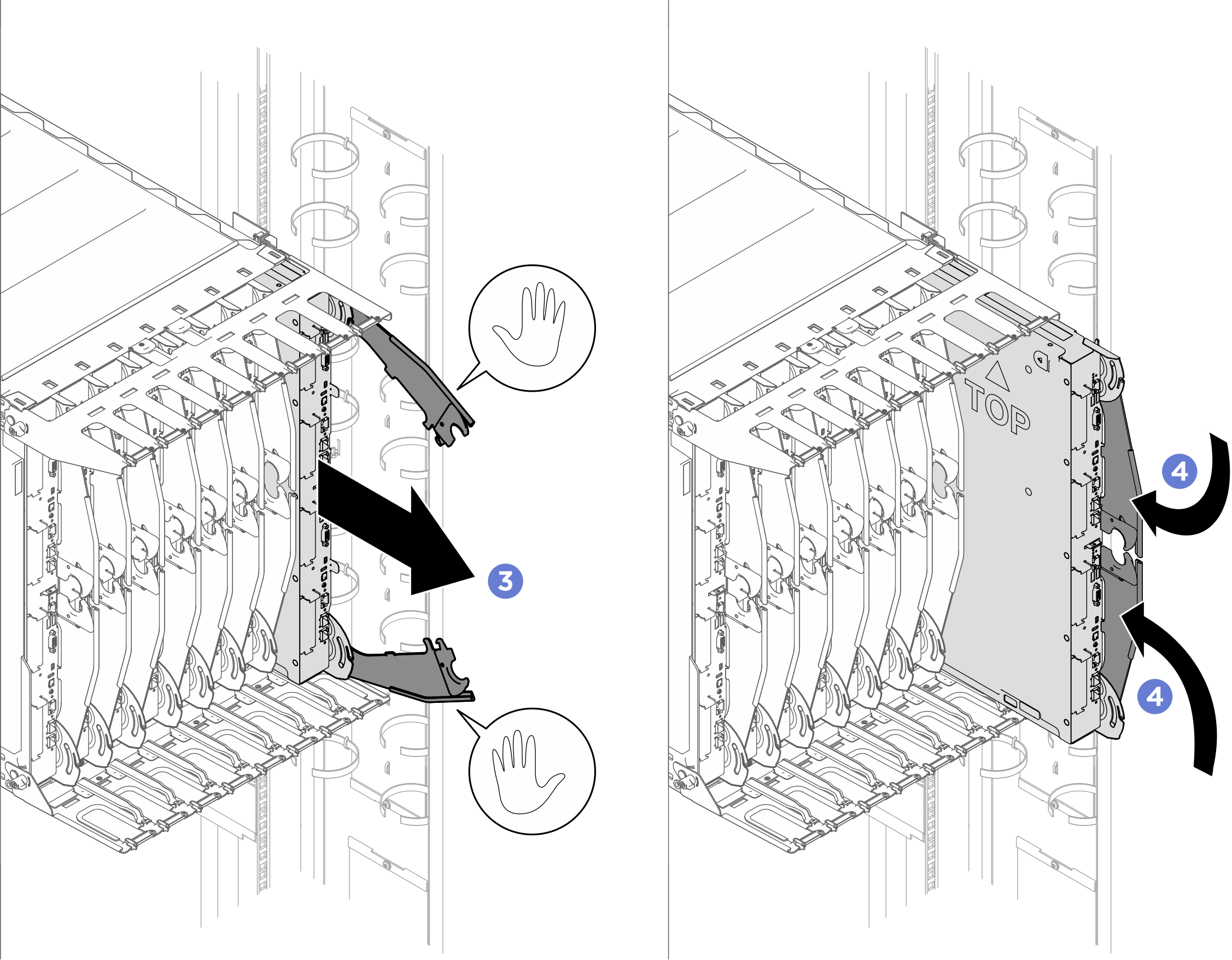
- Adjust the fixture guide fence to the SW position (Single Wide). If the guide fence is not in SW position, lift the guide fence, and re-install it to the SW slots.
Fence label description Full description SW Single Wide PCS Power Conversion Station DW Double Wide Figure 5. Fixture guide fence set to SW position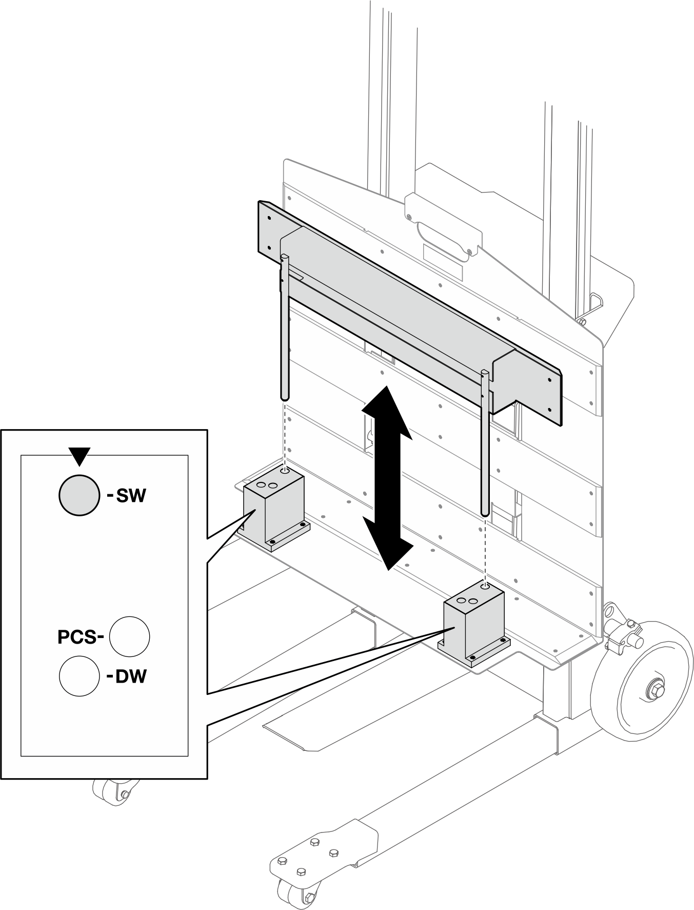
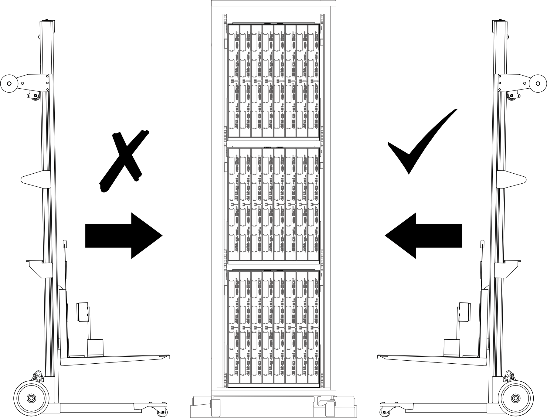
- Move the lift tool assembly to the front of the rack. Make sure the fixture front side is facing the tray back side.Figure 6. Lift tool assembly placement in front of the rack
- Adjust the lift tool so that the fixture bottom aligns with the tray bottom, and the fixture front side is in parallel to the tray back side.NoteRotate the lift tool handle
clockwise to raise the fixture; counterclockwise to lower the fixture. 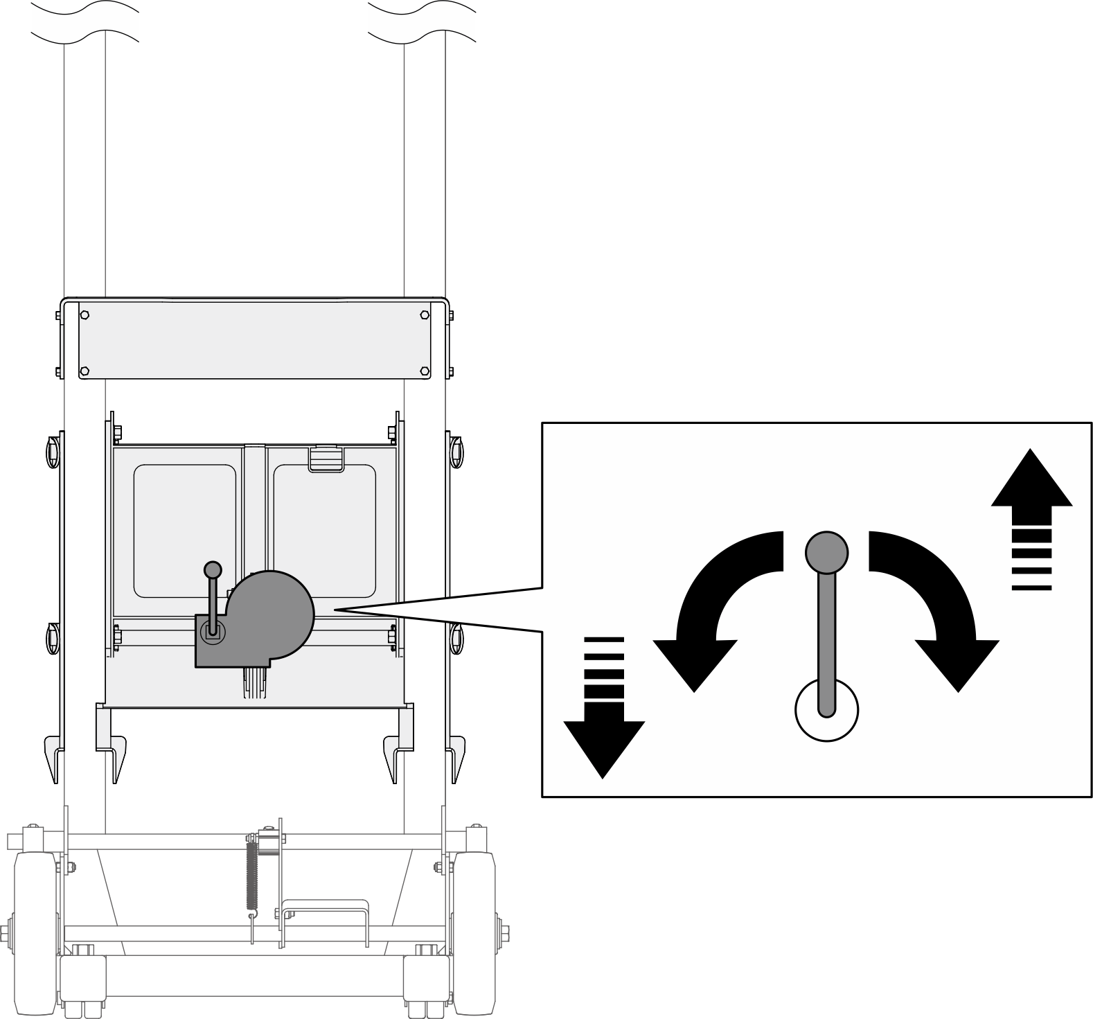 Figure 7. Aligning fixture and the tray bottoms
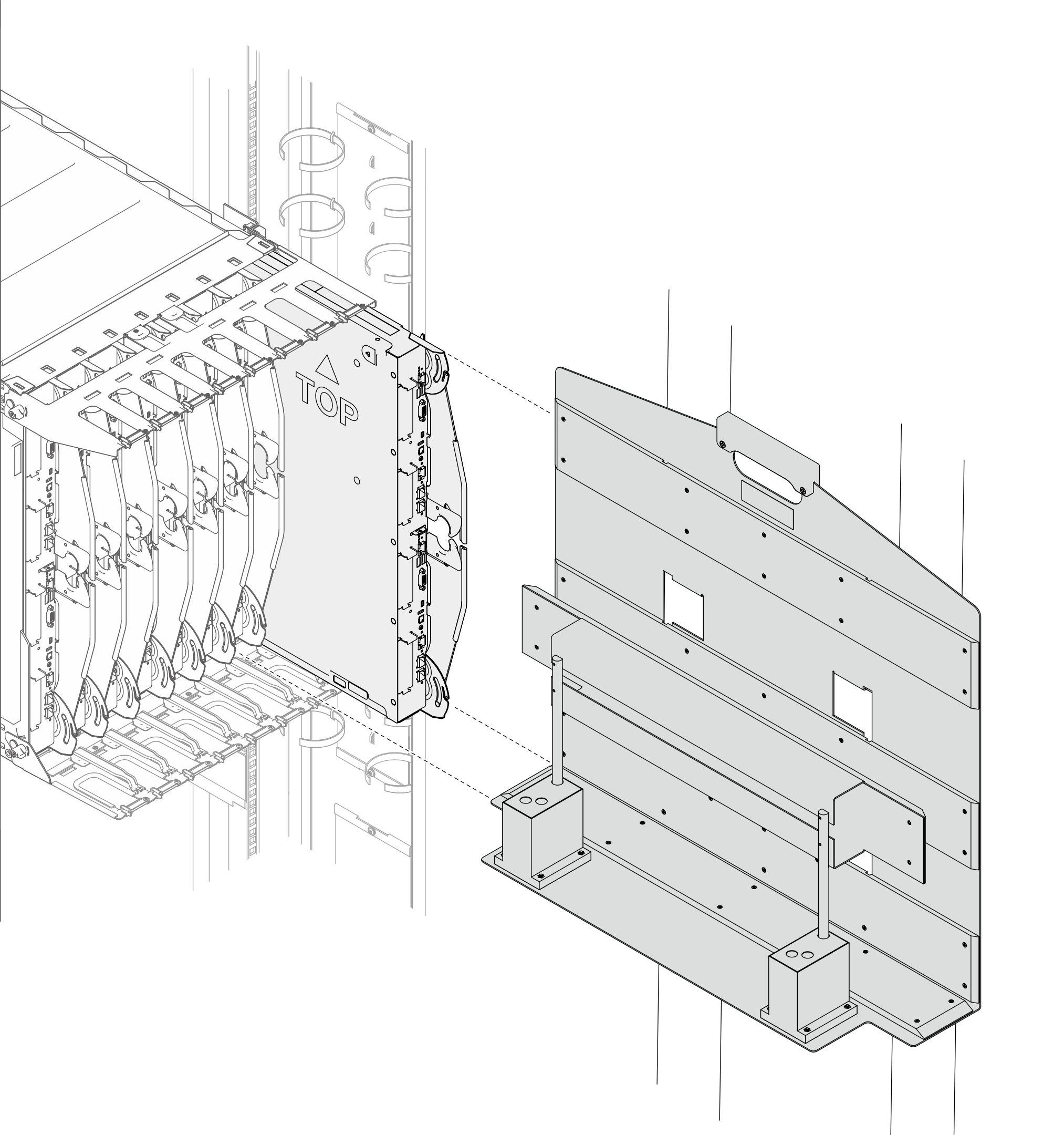 Figure 8. Aligning fixture front side with tray back side
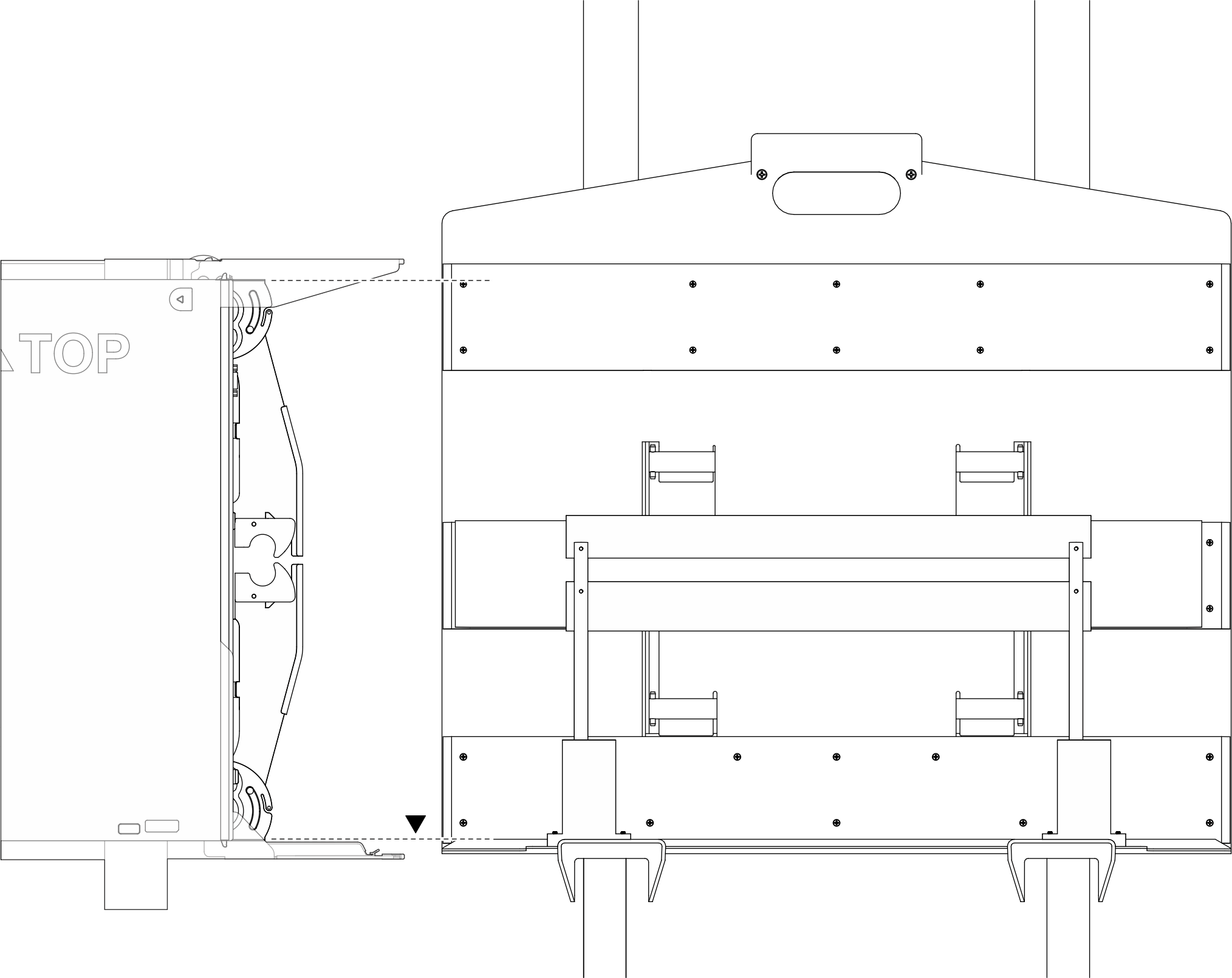
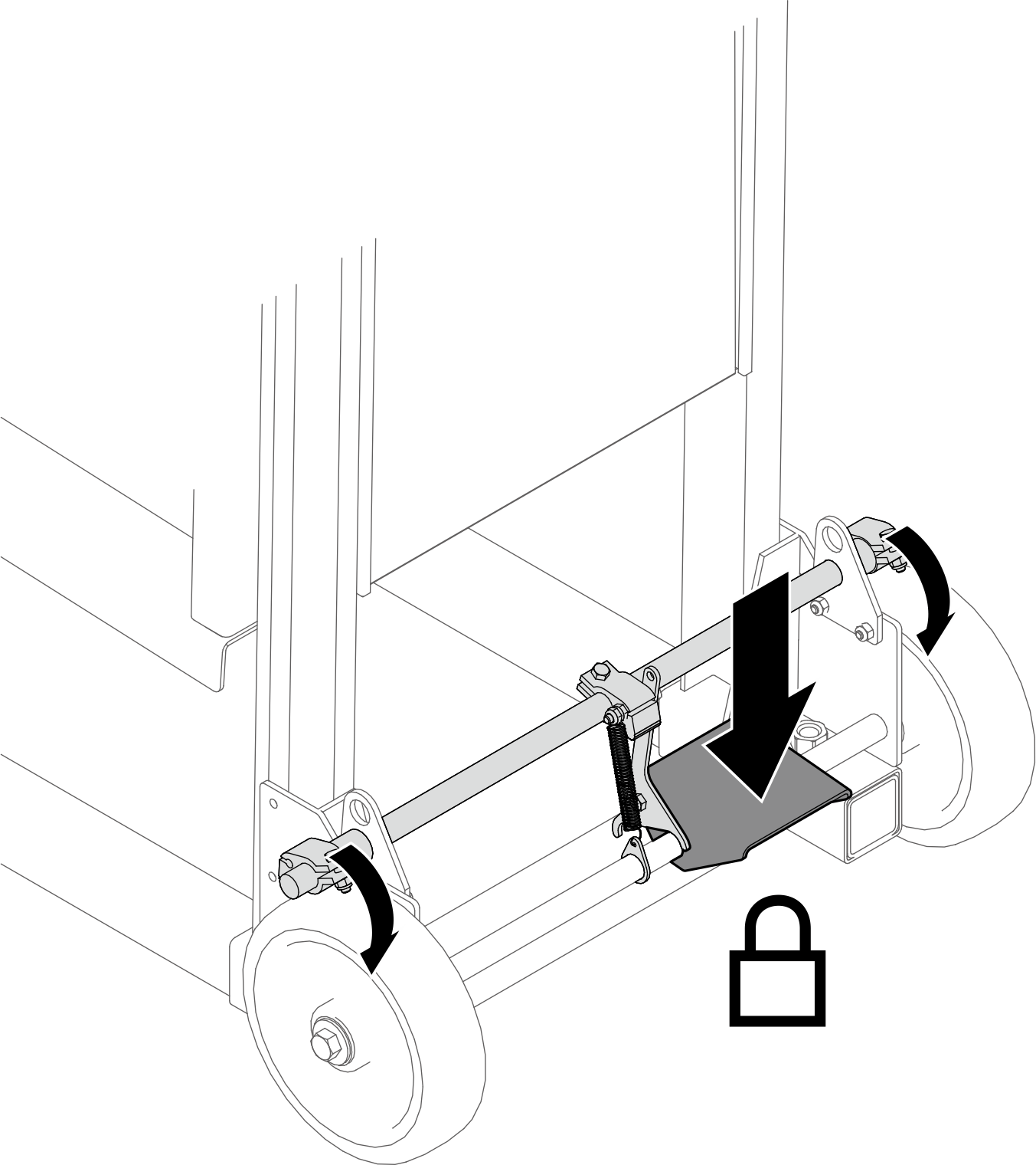
- Push down the foot pedal to lock the wheel brake of the lift tool.Figure 9. Locking the lift tool wheel brake
- Transfer the tray to the fixture.
- Grab the top and bottom parts of the tray.
- Slide the tray onto the fixture.
- Make sure the tray is properly seated in the fixture.
NoteTray weight estimation: 37.215 kg (82.059 lbs)Figure 10. Transferring the tray to the fixture
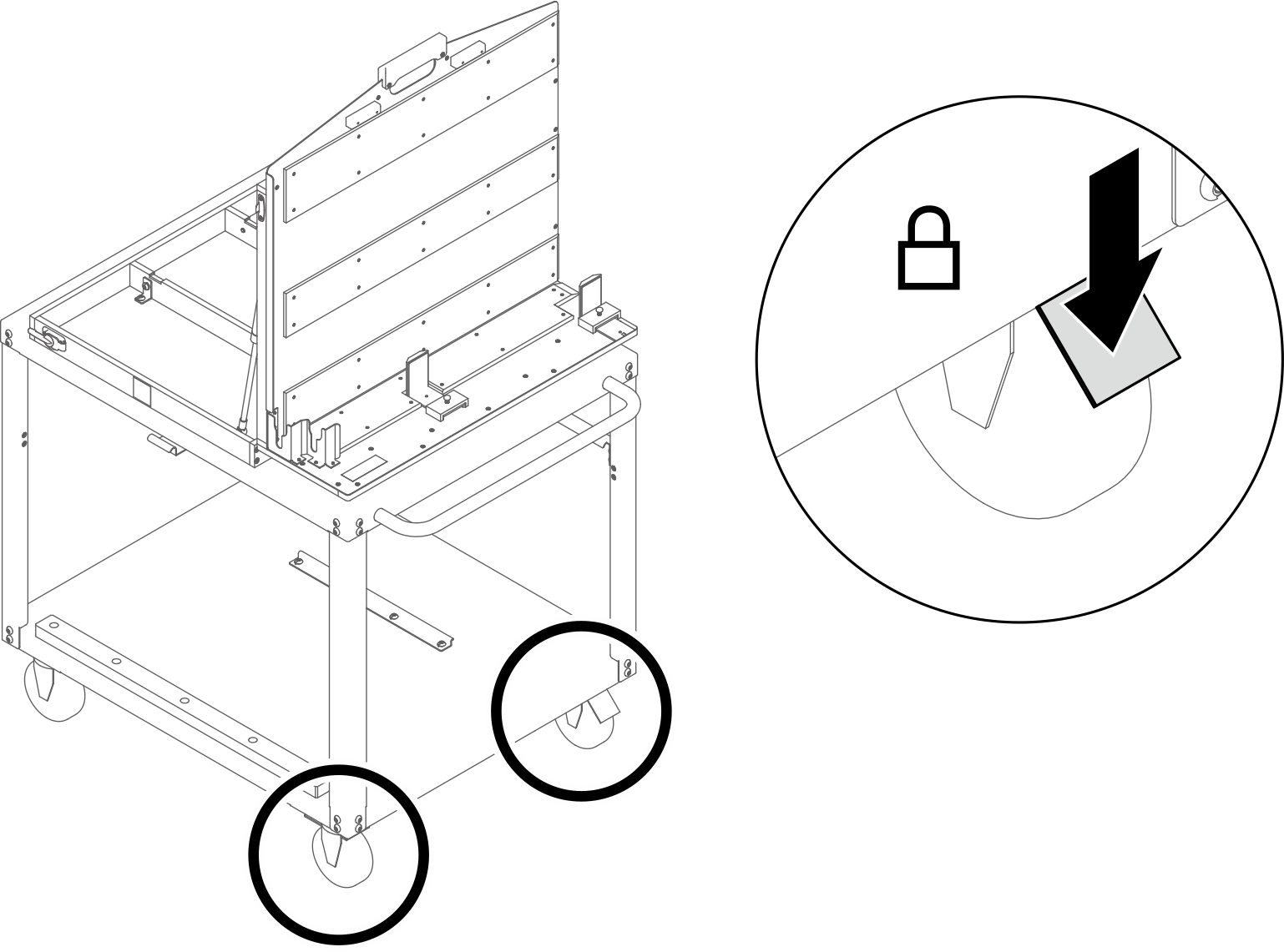
- Push down the foot pedal to lock the wheel brakes on the rotate fixture cart.Figure 11. Locking the cart wheel brakes
- Open the rotate fixture if it is closed.
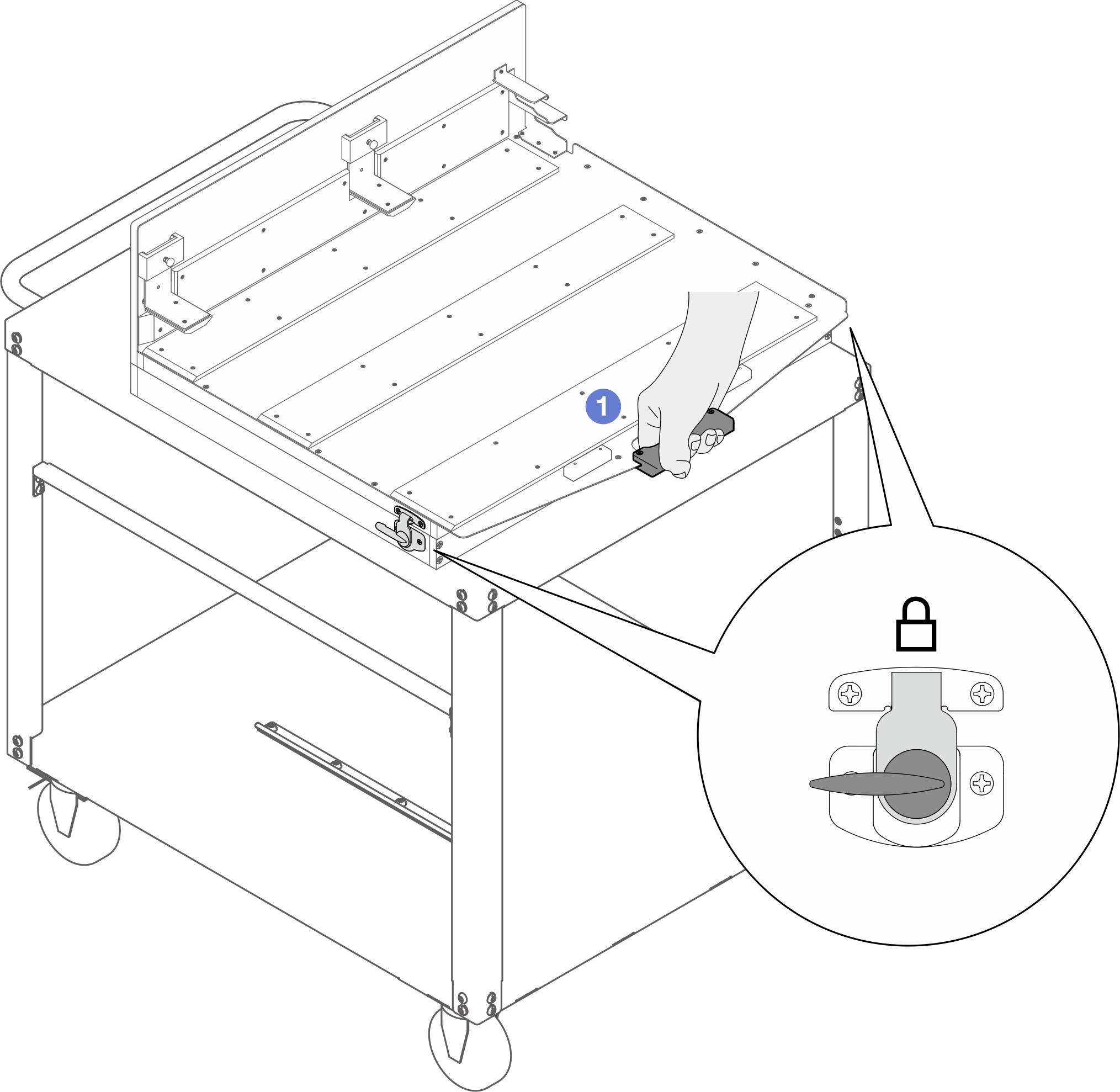
- Grab the handle, and hold the handle down with extra force.Figure 12. Holding down the rotate fixture handle
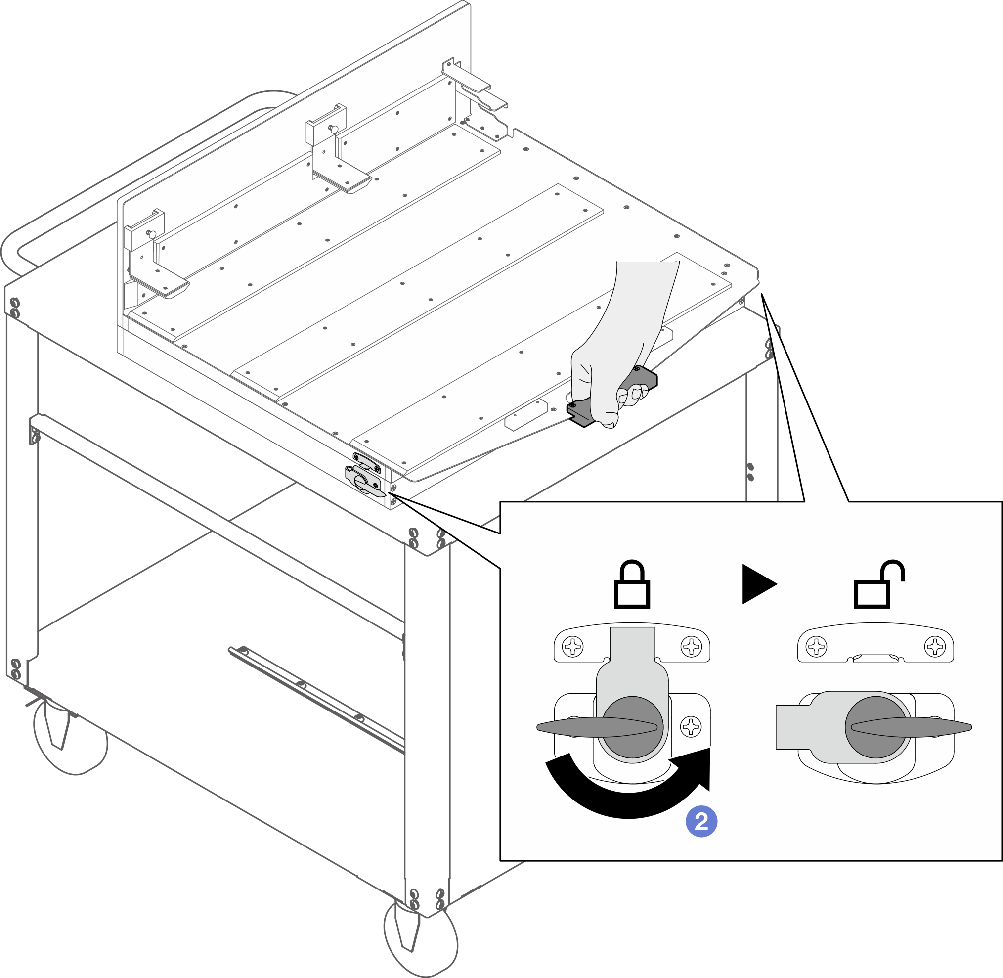
- Keep holding down the handle. Meanwhile, rotate the latch counterclockwise until it is unlocked. Make sure to unlock the latches on the right and left sides of the fixture.AttentionMake sure you are holding down the handle while unlocking the latches.Figure 13. Unlock the rotate fixture latches
- Hold the handle; then, slowly rotate it upward until it stands vertically.
AttentionMake sure you are holding the handle while opening the rotate fixture.Figure 14. Open the rotate fixture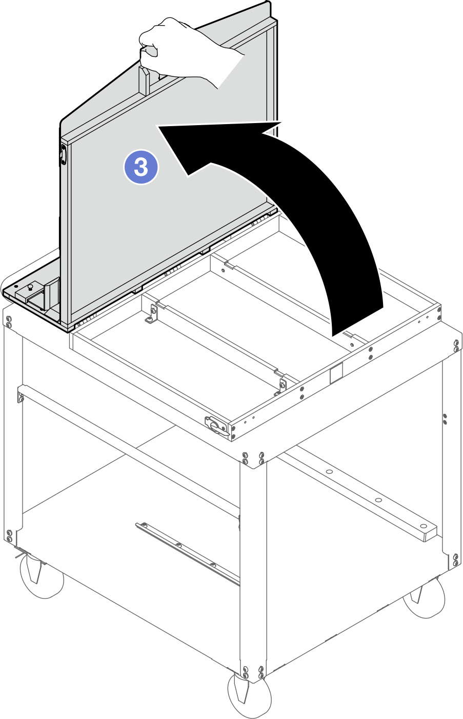
- Move the lift tool assembly to the right side of the rotate fixture cart assembly (when viewed in front of the rotate fixture) as shown in the illustration below. Adjust the lift tool so that the lift tool fixture bottom aligns with the rotate fixture bottom, and the sides of both fixtures are in parallel.NoteRotate the lift tool handle
clockwise to raise the fixture; counterclockwise to lower the fixture. Figure 15. Aligning lift tool fixture and rotate fixture bottoms and sides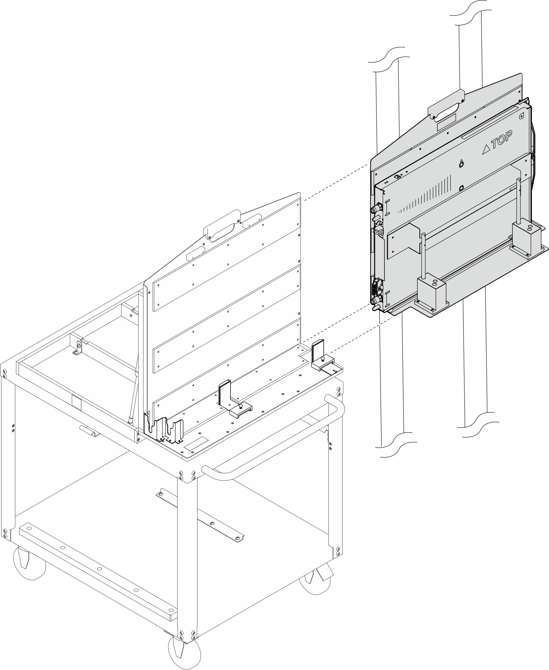
- Push down the foot pedal to lock the wheel brake of the lift tool.Figure 16. Locking the lift tool wheel brake
- Adjust the angle brackets on the rotate fixture.
- Adjust the side angle bracket: Lift up the plunger. Slide angle bracket backwards and release the plunger. Keep sliding bracket until plunger seats into innermost hole.
- Adjust the inner angle bracket: Lift up the plunger.
 Slide angle bracket forward and release plunger.
 Keep sliding bracket until plunger seats into outermost hole
Figure 17. Adjusting the angle brackets of the rotate fixture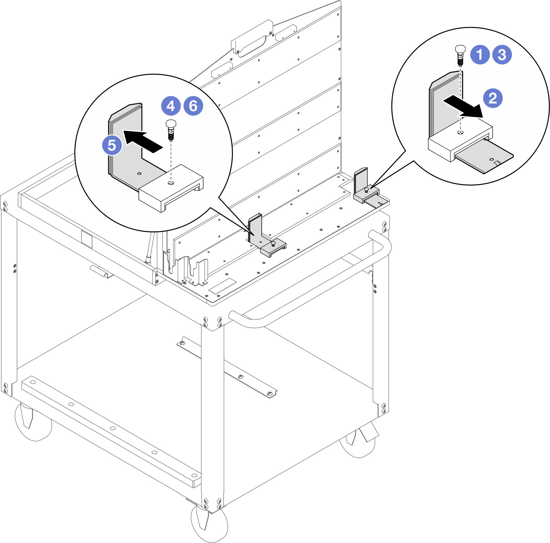
- Adjust the side angle bracket:
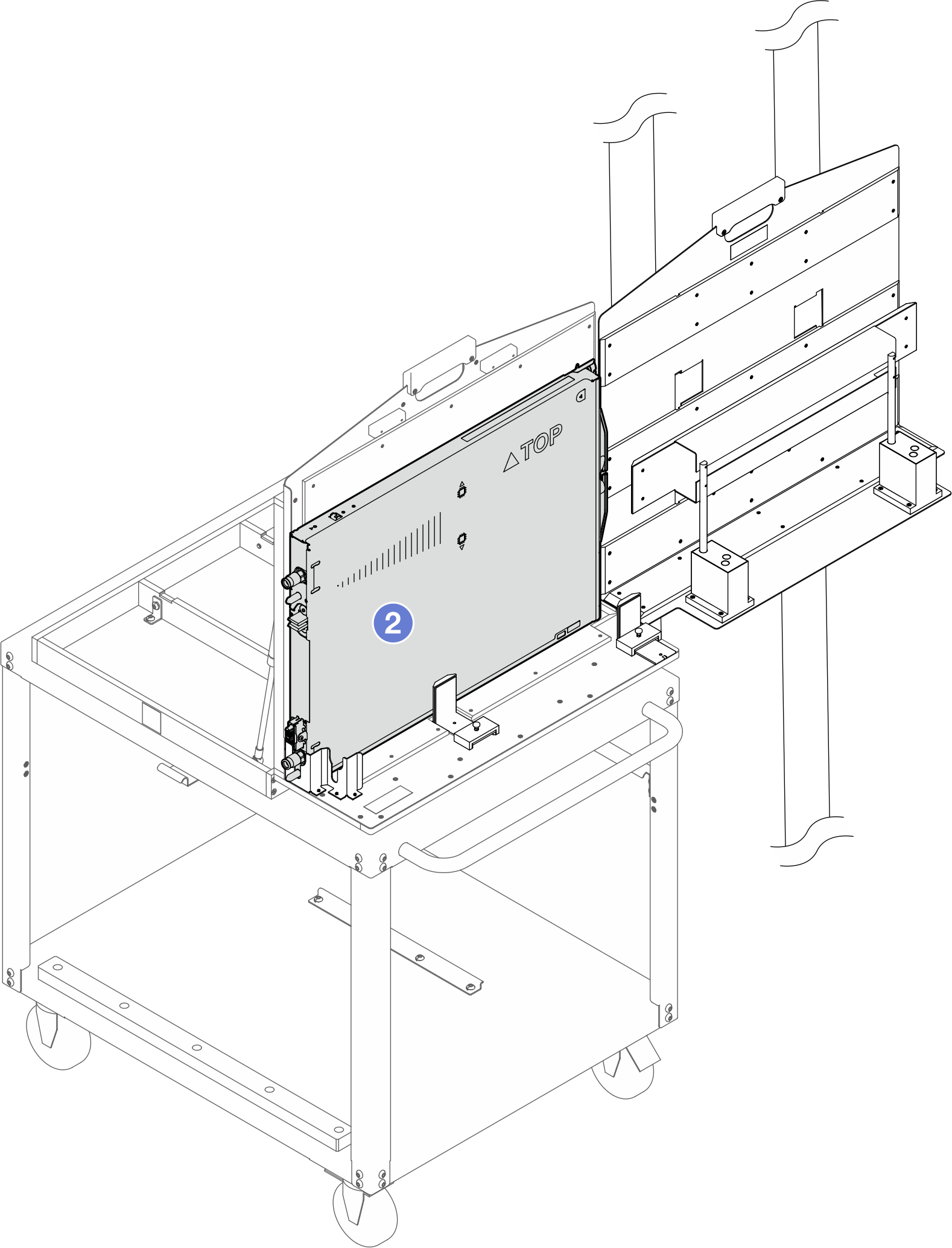
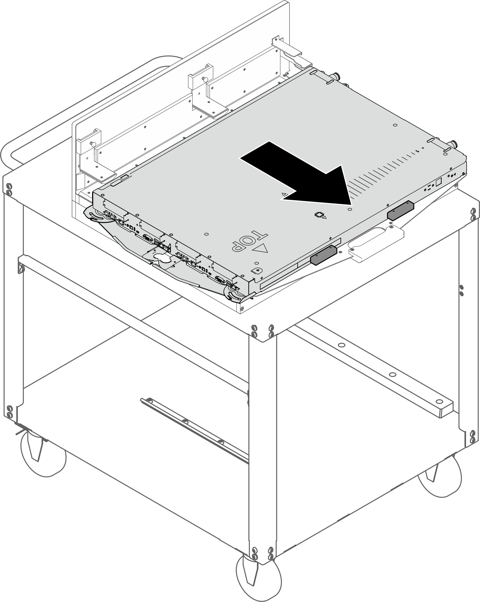
- Transfer the tray to the rotate fixture.
- Slide the tray to the rotate fixture until it is partially seated in the rotate fixture.
- Slide the tray all the way into the fixture until the tray quick connect is seated in the bracket at the end of the fixture.
Figure 18. Transferring the tray to the rotate fixture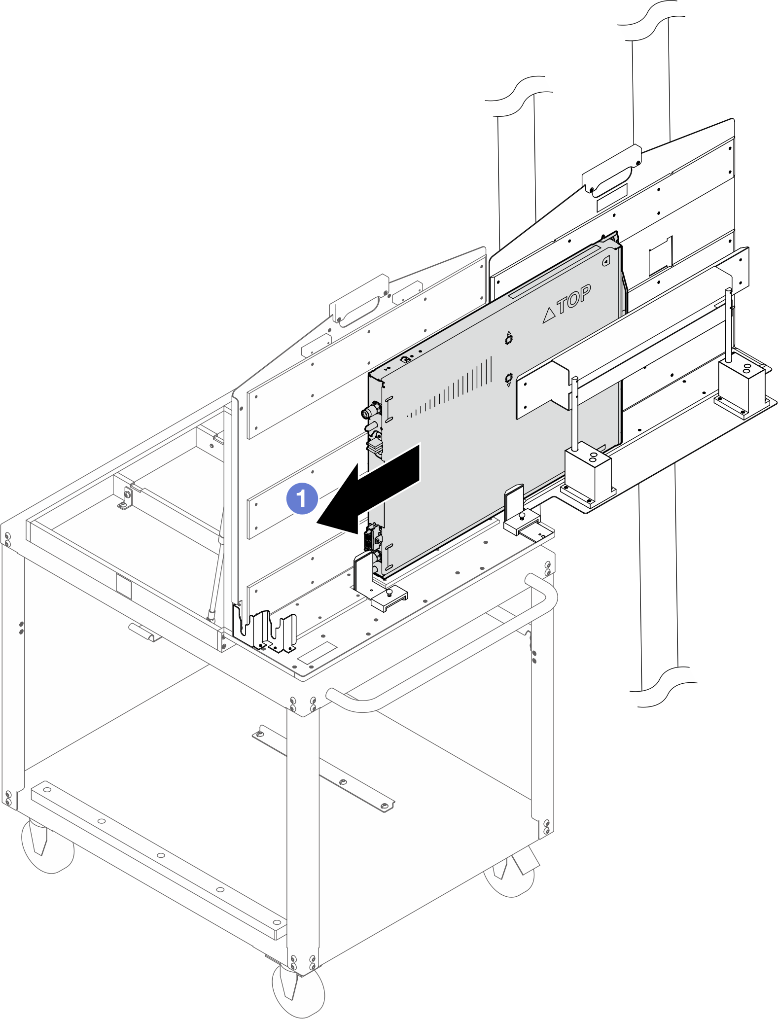
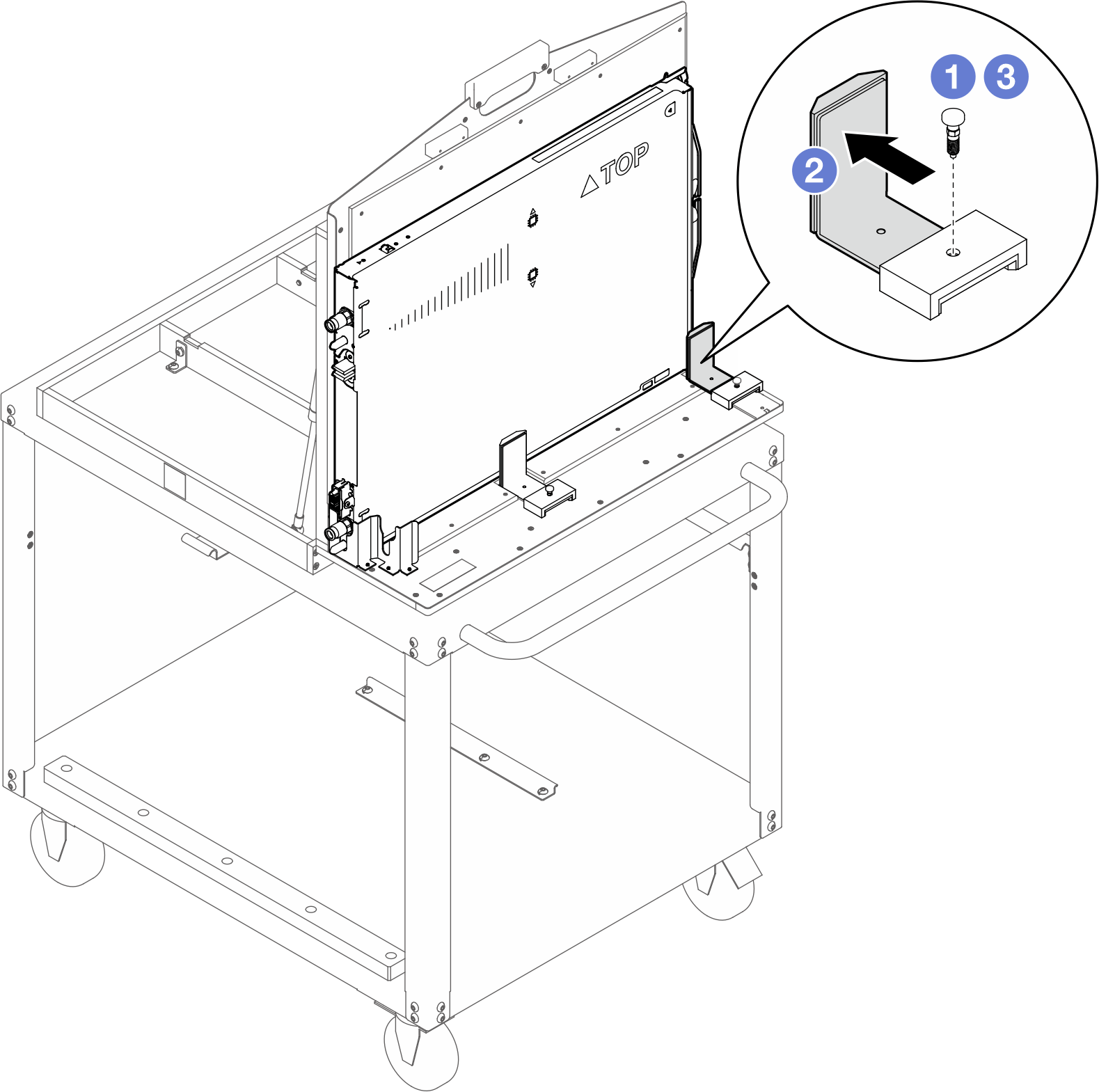
- Adjust the side angle bracket: Lift up the plunger. Slide angle bracket forward and release the plunger. Keep sliding bracket until plunger seats into outermost hole.Figure 19. Adjusting the side angle bracket
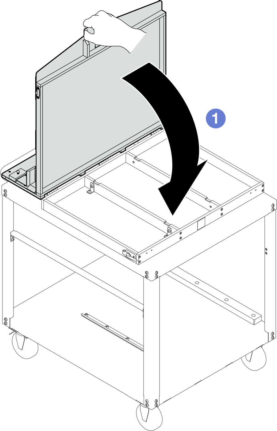
- Close the rotate fixture.
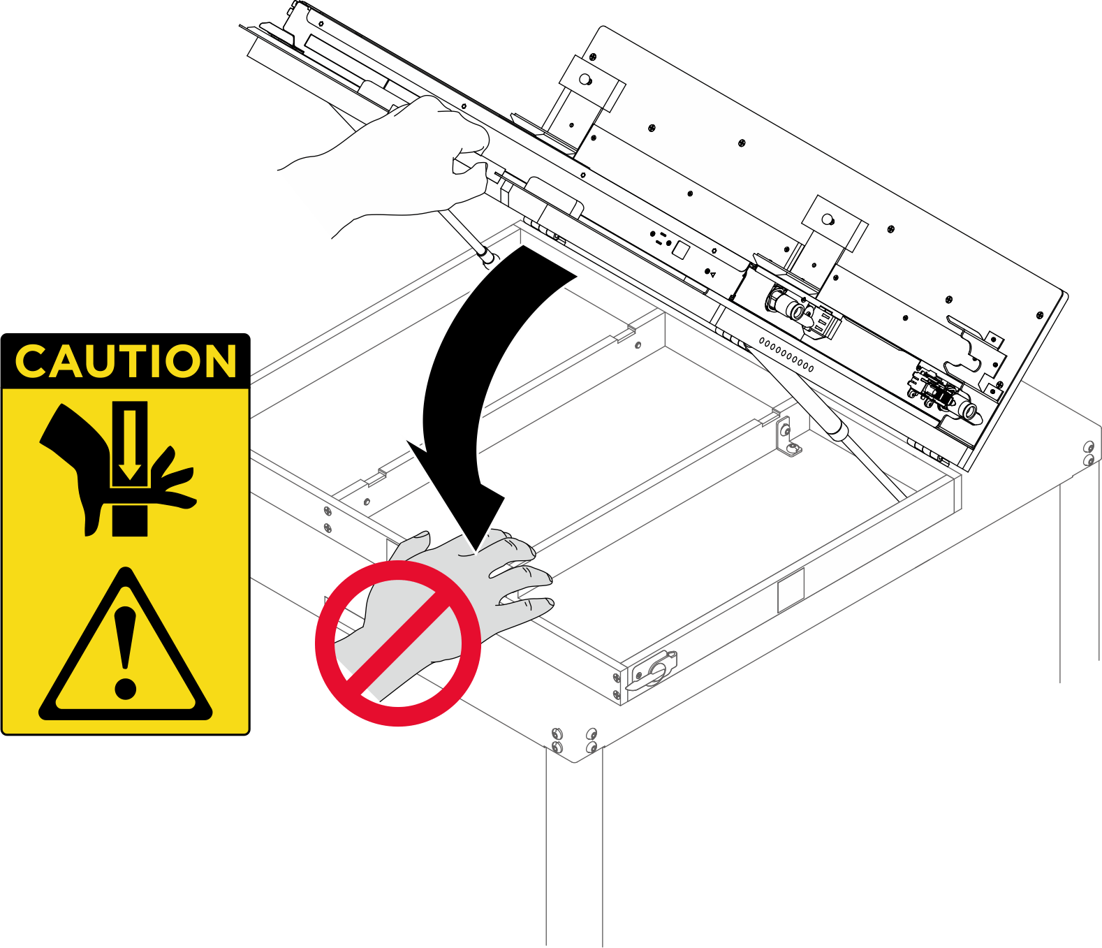
- Stand in front of the backside of the rotate fixture. Grab the handle; then, pull down the rotate fixture until the fixture lays flat on the cart top.AttentionDO NOT put your hands on the support bars in order to prevent injury.Figure 20. Avoid placing hands on the support barsFigure 21. Rotate the rotate fixture plate to the closed position.
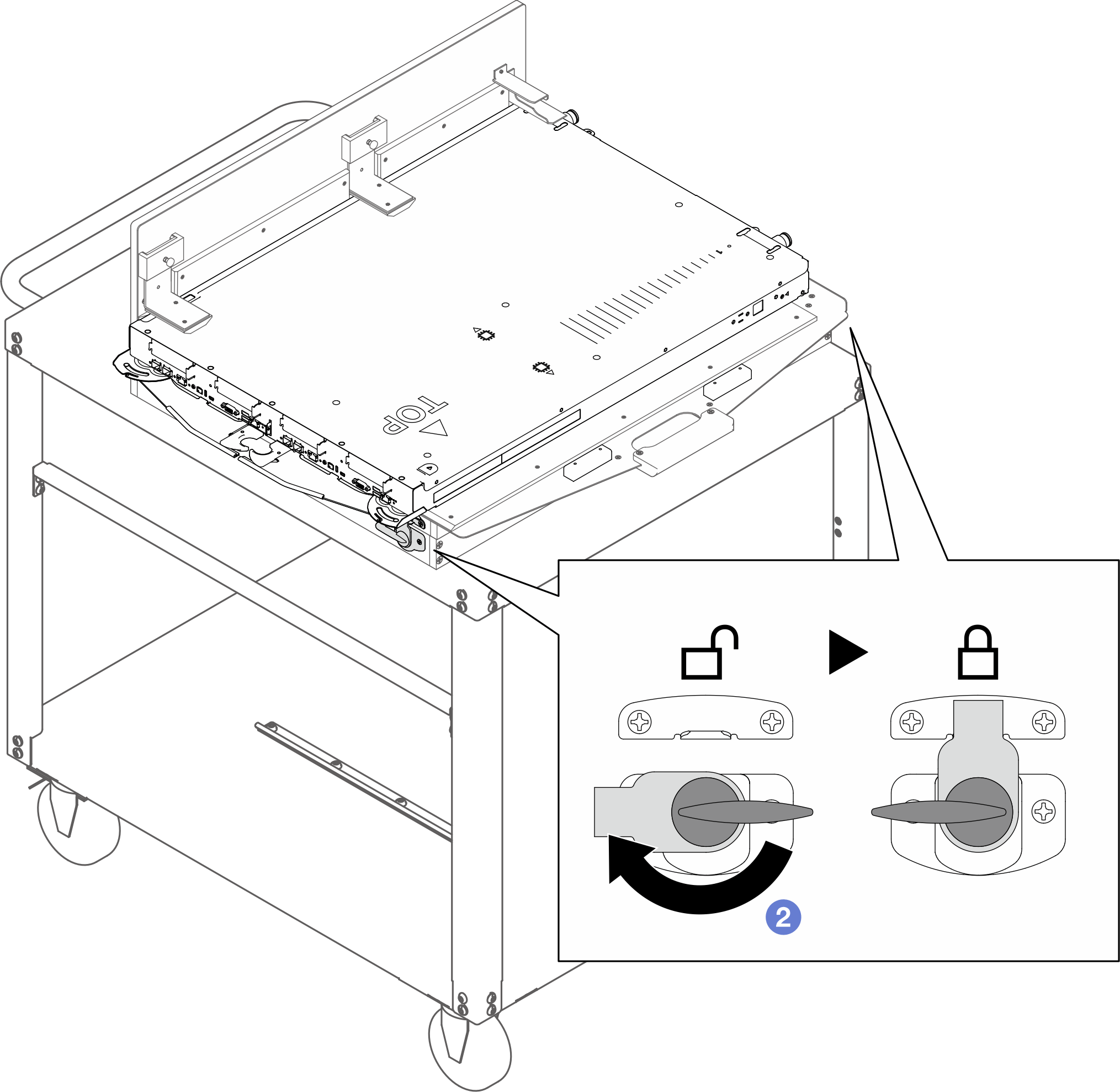
- Rotate the latch clockwise until it is locked. Make sure to lock the latches on the right and left sides of the fixtureFigure 22. Locking the rotate fixture latches
- Slide the tray towards fixture handle until it hits the stoppers near the handle. The tray should be clear of the angle brackets.AttentionS040CAUTIONProtective gloves should be worn for this procedure.
The tray might be very hot. Wait several minutes to let the tray cool before removing the tray cover.
If you are instructed to return the component or optional device, follow all packaging instructions, and use any packaging materials for shipping that are supplied to you.