Gap pad identification and location
Follow the information in this section to identify shape, location, replacing scenarios, and instruction on the gap pads used in SC750 V4.
Installation guidelines for gap pads used in SC750 V4
See the following for gap pads and putty pads used in SC750 V4:
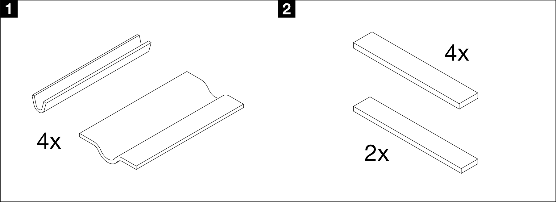
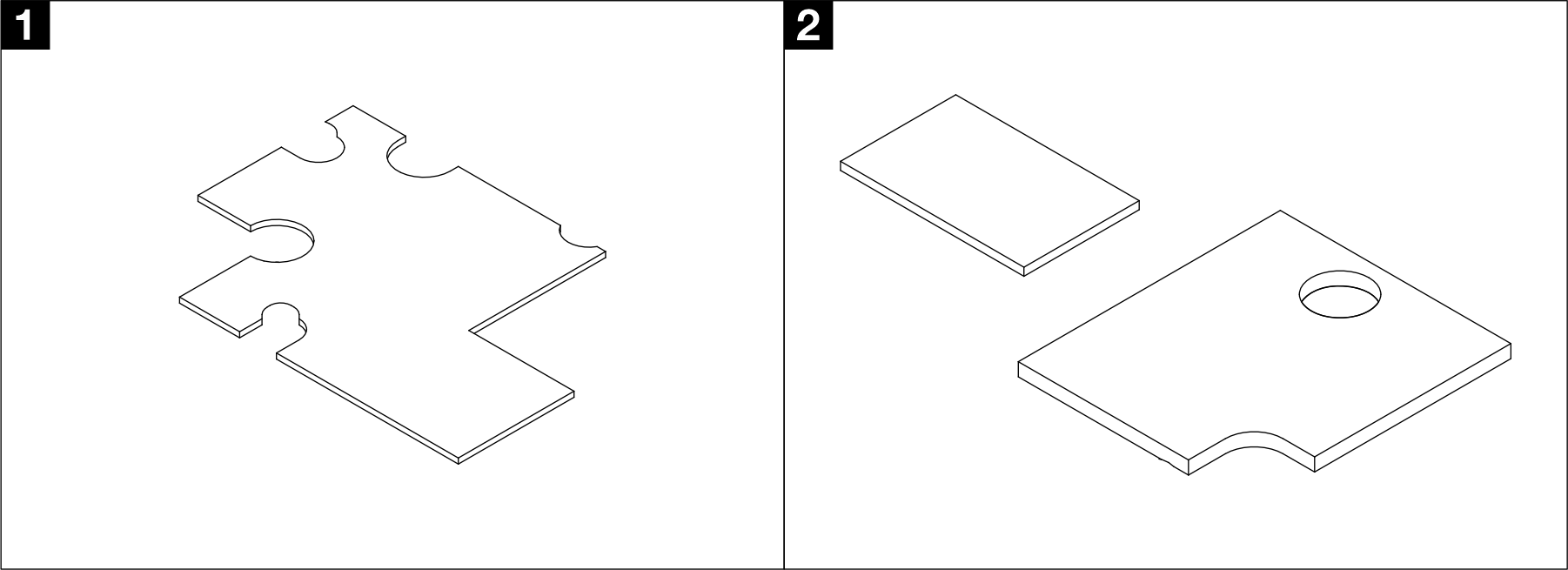
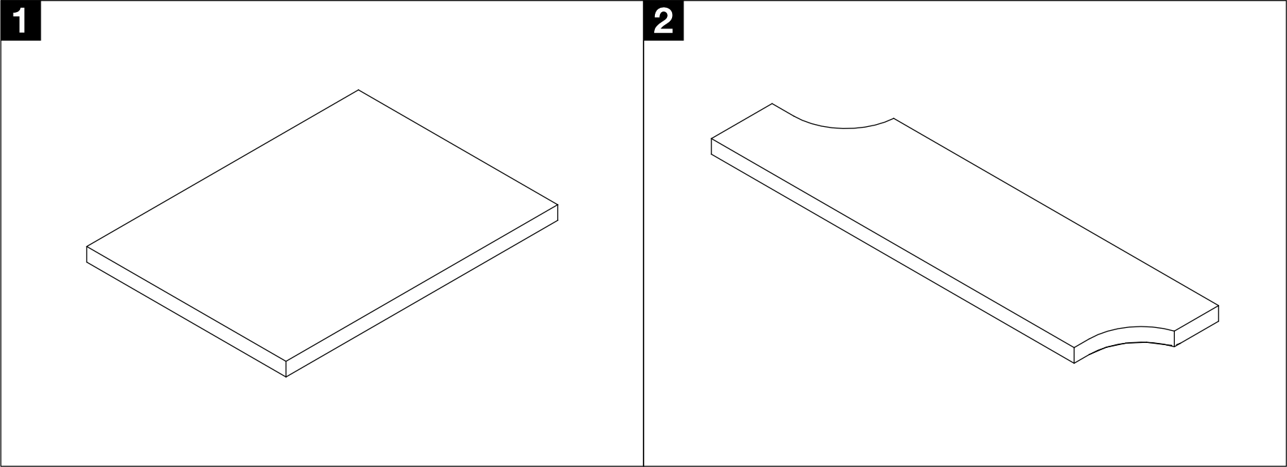
Water loop gap pads
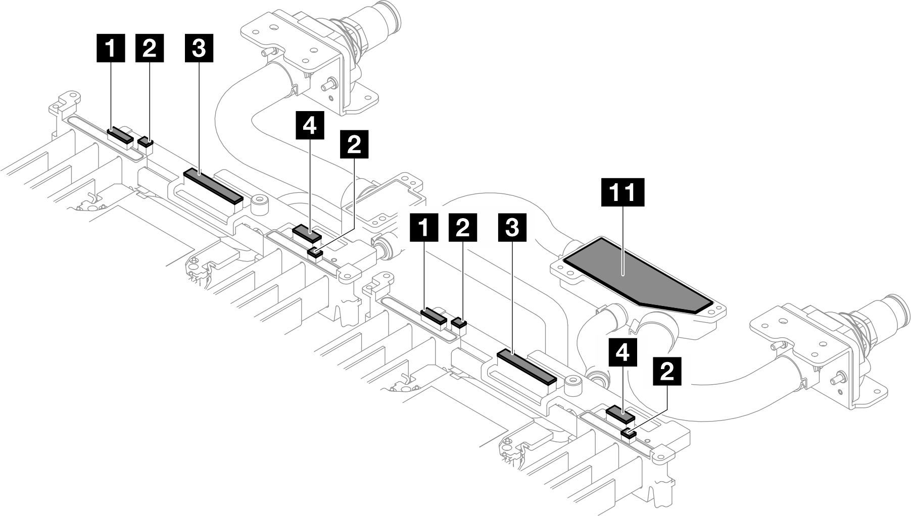

| Pad number | Component installation requiring the pads | Scenario requiring pad replacing | Pad attaching location | Pad attaching instructions |
|---|---|---|---|---|
1, 2, 3, 4 | Replace the pad when the pad on water loop is damaged or detached. | Rear end of the water loop |
| |
11 | Replace the pad when the pad on water loop is damaged or detached. | Mixing chamber on the rear end of the water loop |
| |
5, 6, 7, 8, 9 10, 12, 13, 14, 15 | Replace the pad when the pad on water loop is damaged or detached. | Front end of the water loop |
|
VR cold plate gap pads
| Pad number | Component installation requiring the pads | Scenario requiring pad replacing | Pad attaching location | Pad attaching instructions |
|---|---|---|---|---|
| 1 | Replace the pad when the pad on VR cold plate is damaged or detached. | Top side of the VR cold plate | Peel off the transparent plastic film on the pad, and attach this side to the cold plate. | |
| 2 | Single-use gap pad Replace the pads whenever the VR cold plate is removed. | Bottom side of the VR cold plate |
|
ConnectX-7 NDR adapter gap pads
| Pad number | Component installation requiring the pads | Scenario requiring pad replacing | Pad attaching location | Pad attaching instructions |
|---|---|---|---|---|
| 1 | Single-use gap pad Replace the pads whenever the ConnectX-7 NDR 400 riser assembly is removed. | ConnectX-7 NDR 400 interface plate |
| |
| 2 | Single-use gap pad Replace the pads whenever the ConnectX-7 NDR 200 riser assembly is removed. | ConnectX-7 NDR 200 interface plate |
ConnectX-8 adapter gap pads
| Pad number | Component installation requiring the pads | Scenario requiring pad replacing | Pad attaching location | Pad attaching instructions |
|---|---|---|---|---|
| 1 | Single-use gap pad Replace the pads whenever the ConnectX-8 riser assembly is removed. | ConnectX-8 interface plate |
| |
| 2 | Single-use gap pad Replace the pads whenever the ConnectX-8 riser assembly is removed. | ConnectX-8 interface plate |
OPA 400 adapter gap pads

| Pad number | Component installation requiring the pads | Scenario requiring pad replacing | Pad attaching location | Pad attaching instructions |
|---|---|---|---|---|
| 1 | Single-use gap pad Replace the pads whenever the OPA 400 riser assembly is removed. | OPA 400 interface plate |
|
E3.S drive gap pads

| Pad number | Component installation requiring the pads | Pad attaching location | Pad replacing scenario | Pad attaching instructions |
|---|---|---|---|---|
| 1 | Top side of the E3.S middle cold plate | Replace the pad when the pad on the E3.S middle cold plate is damaged or detached |
| |
| 2 | Bottom side of the E3.S middle cold plate | Single-use gap pad Replace the pad whenever the E3.S middle cold plate is removed. |
| |
| 3 | E3.S drive heat sink | Replace the pad when the pad on the E3.S drive heat sink is damaged or detached. |
| |
| 4 | Water loop | Replace the pad when the pad on the water loop is damaged or detached. |
| |
| 5 | Water loop | Single-use gap pad Replace the pads whenever the E3.S front drive cage is removed. |
|