Install E3.S 1T dual front drive
Use this information to install E3.S 1T dual front drives.
About this task
Screwdriver for PH 1 screws
Storage Gap Pad Kit (SC750 V4)
Storage Conduction Plate (if installing the E3.S 1T dual front drive for the first time)
For gap pad location and instruction, see Gap pad identification and location.
Before replacing the gap pad, gently clean the surface with an alcohol cleaning pad.
Hold the gap pad carefully to avoid deformation. Make sure no screw hole or opening is blocked by the gap pad material.
Read Installation Guidelines and Safety inspection checklist to ensure that you work safely.
- A video of this procedure is available at YouTube.
Procedure
- Install top-side cooling drives. (For installing bottom-side cooling drives, see Step 2.)
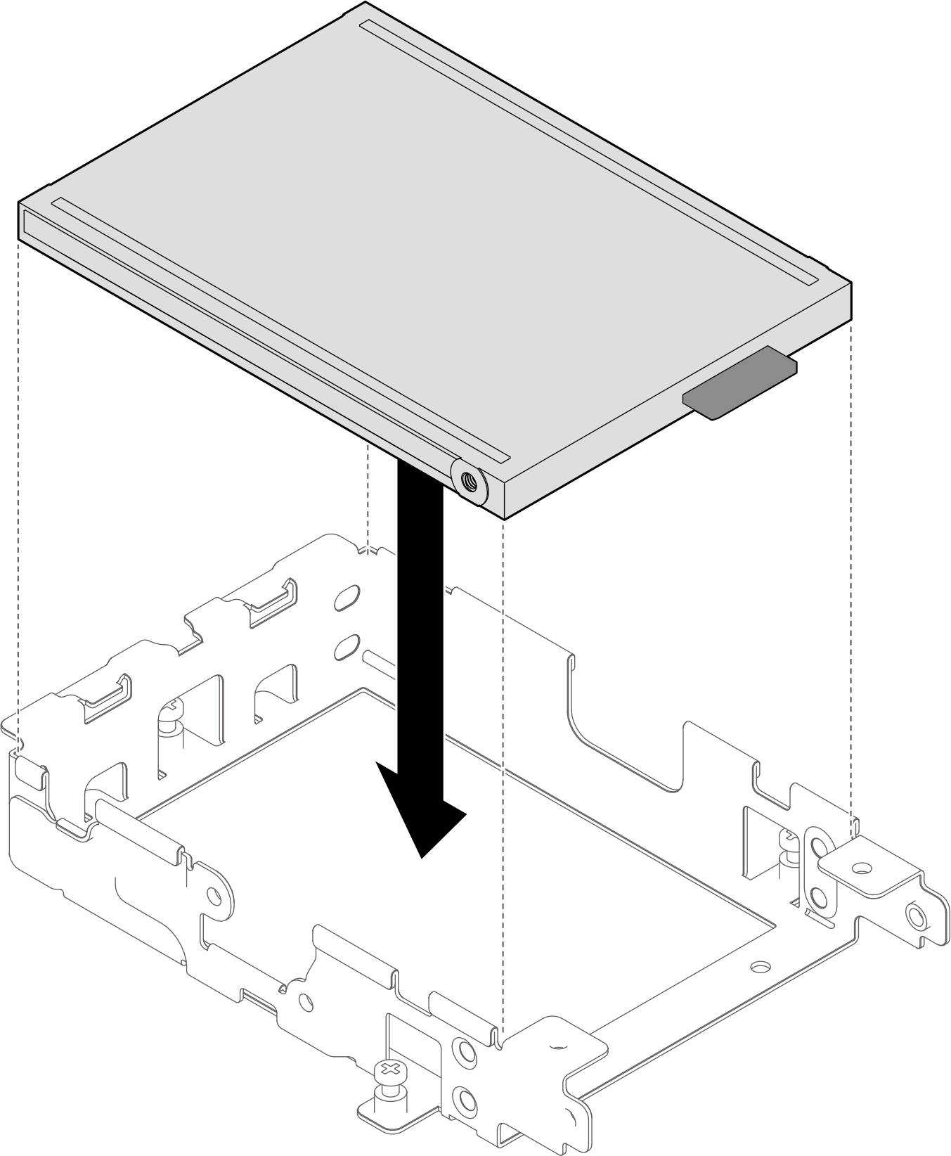
- Install the first top-side cooling drive. Make sure the drive connector position is the same as shown in the illustration below.Figure 1. Installing first top-side cooling drive
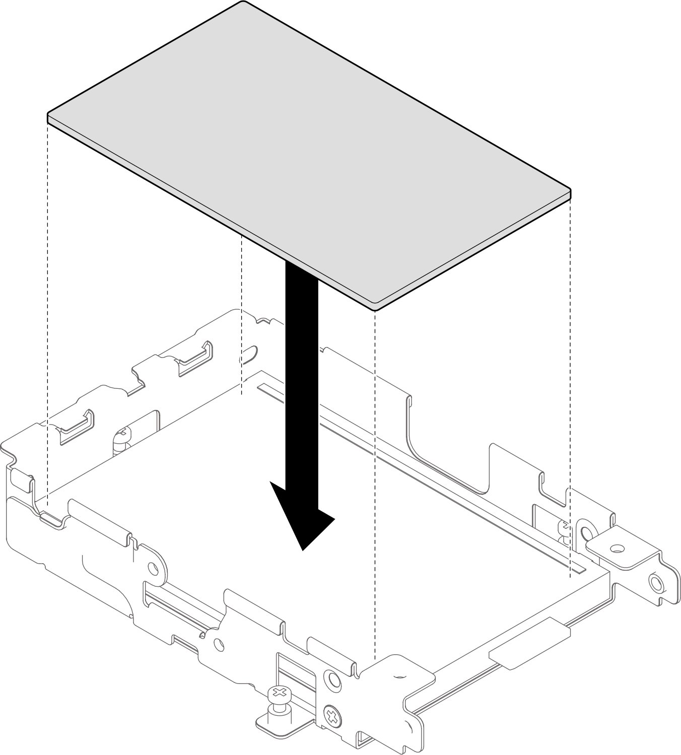
- Place the spacer on top of the first drive.Figure 2. Placing the spacer on the top-side cooling drive
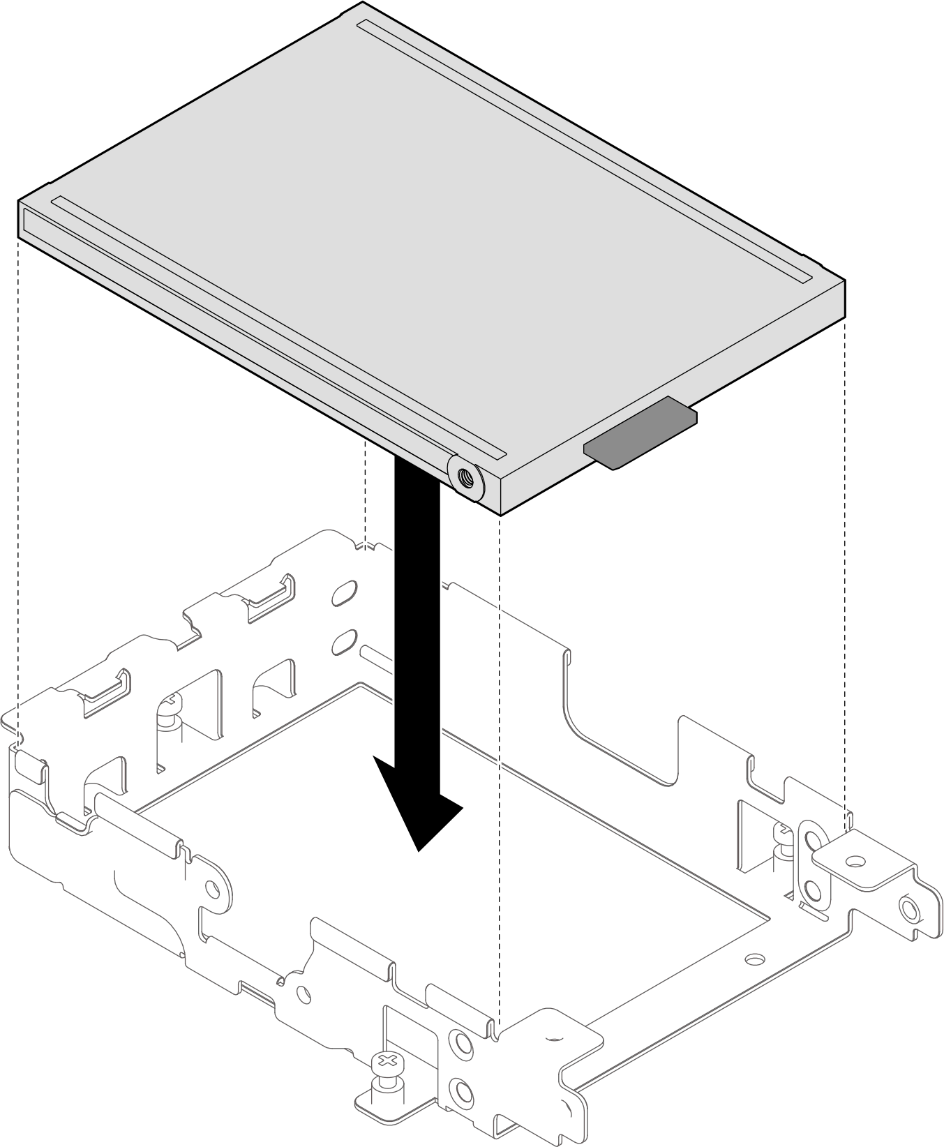
- Install the second top-side cooling drive to the drive cage. Make sure the drive connector position is the same as shown in the illustration below. Afterwards, proceed to Step 3.Note
Pay attention to the drive connector position in the drive cage. The drive connector position of the two drives in the drive cage should be different.
Figure 3. Installing second top-side cooling drive
- Install the first top-side cooling drive. Make sure the drive connector position is the same as shown in the illustration below.
- Install bottom-side cooling drives. (For installing top-side cooling drives, see Step 1.)
- Install the first bottom-side cooling drive. Make sure the drive connector position is the same as shown in the illustration below.Figure 4. Installing first bottom-side cooling drive
- Place the spacer on top of the first drive.Figure 5. Placing the spacer on the bottom-side cooling drive

- Install the second bottom-side cooling drive to the drive cage. Make sure the drive connector position is the same as shown in the illustration below. Afterwards, proceed to Step 3.Note
Pay attention to the drive connector position in the drive cage. The drive connector position of the two drives in the drive cage should be different.
Figure 6. Installing second bottom-side cooling drive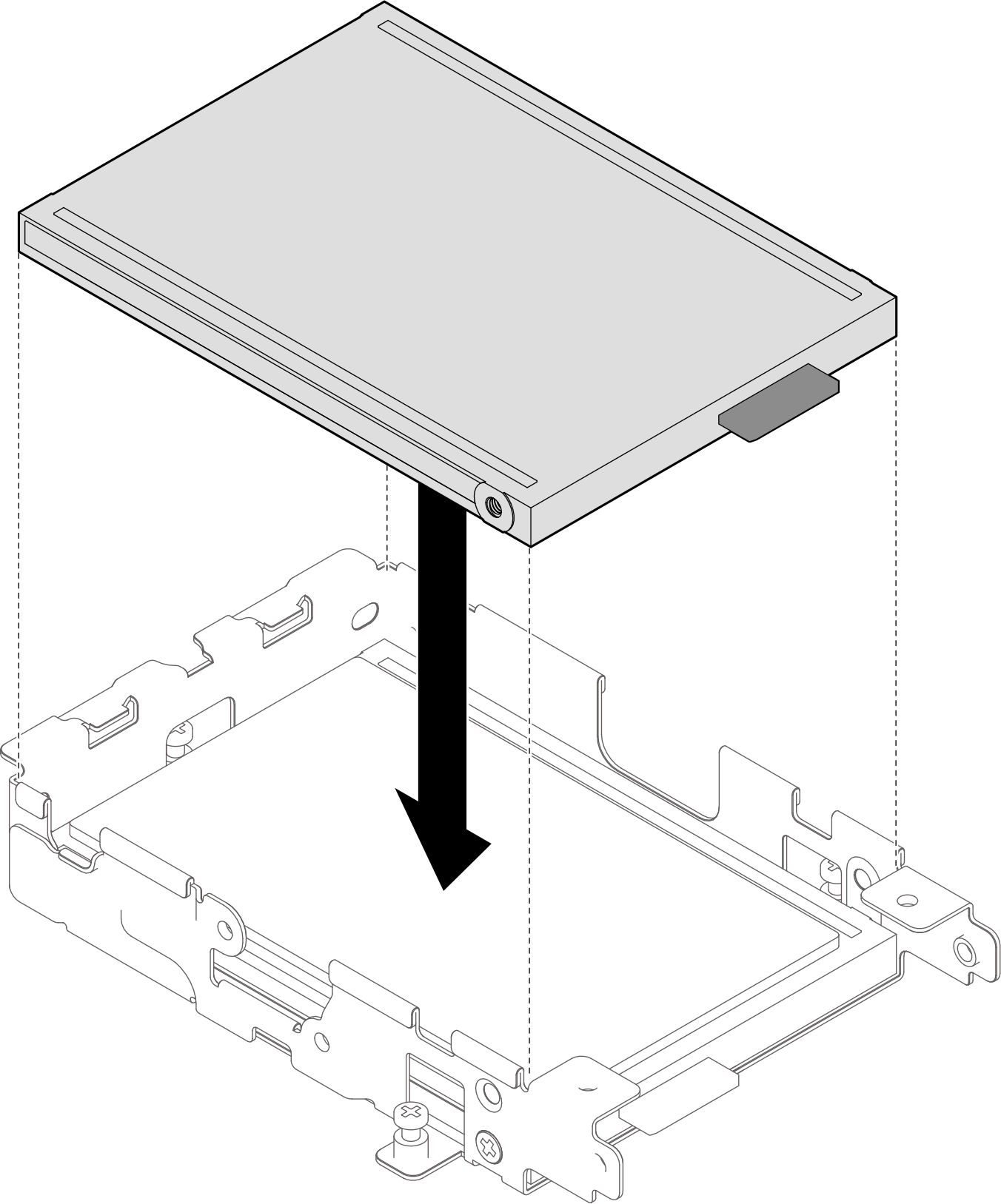
- Install the first bottom-side cooling drive. Make sure the drive connector position is the same as shown in the illustration below.
- Install the eight PH1 screws to secure the drives to the drive cage.Figure 7. Installing screws to the drive cage
- Check the gap pad on heat sink, if it is damaged or detached, replace them with new one.Figure 8. Heat sink gap pad location
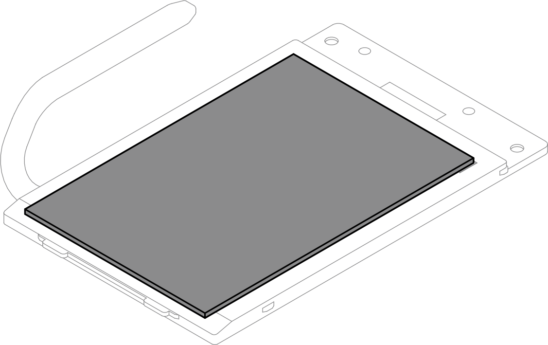
Make sure to follow Gap pad replacement guidelines.
- Install the heat sink to the drive cage.
 Keep the heat sink at an angle, and align the tabs on the heat sink with the slots on drive cage.
 Rotate the heat sink and place it on the drive cage.Figure 9. Installing the heat sink
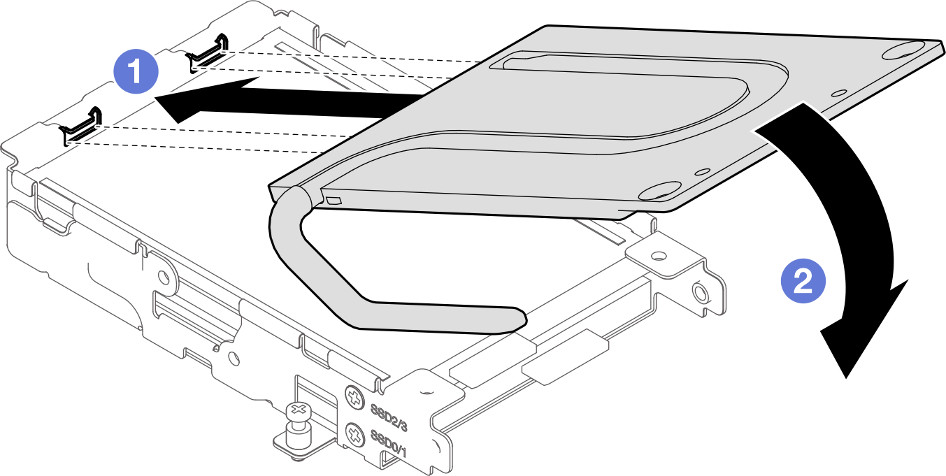
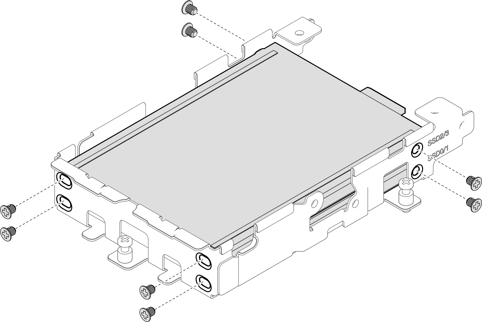
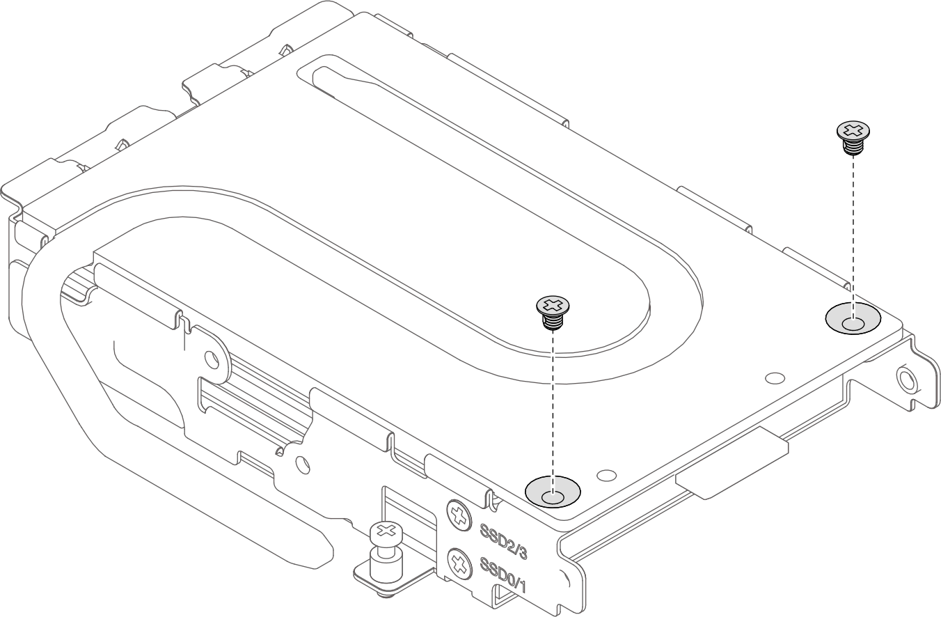
- Install two PH1 screws to secure the heat sink to the drive cage.Figure 10. Installing heat sink screws
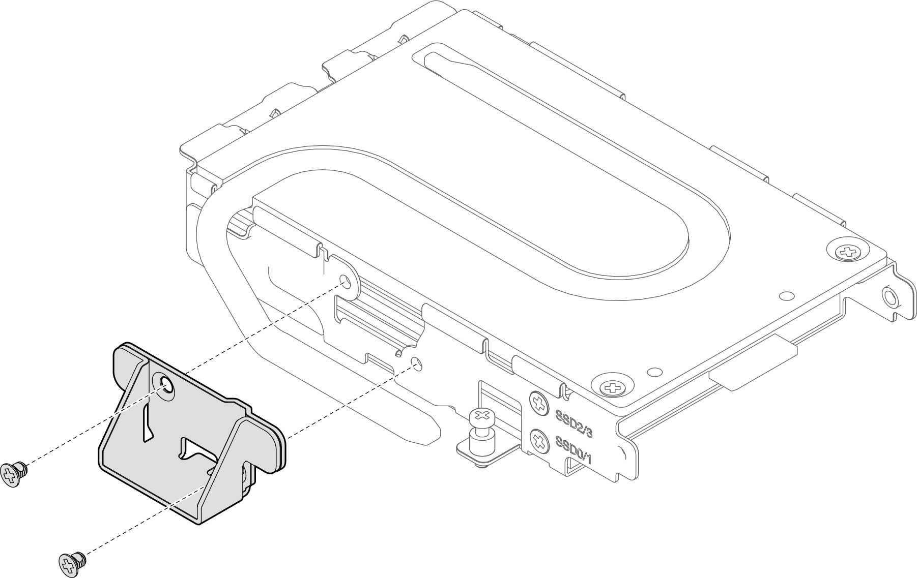
- Install two PH 1 screws to secure the side holder to the drive cage.Figure 11. Installing the side holder
- Connect the cables to the drive.
Table 1. Cable plugger and drive number connection rule From To Plugger marked as 0 or 1 Drive in drive cage slot SSD 0/1 Plugger marked as 2 or 3 Drive in drive cage slot SSD 2/3 NoteDepending on drive configuration, twisting cables may be needed to accommodate the cable pluggers to the drive cage.Figure 12. Connecting cables to drives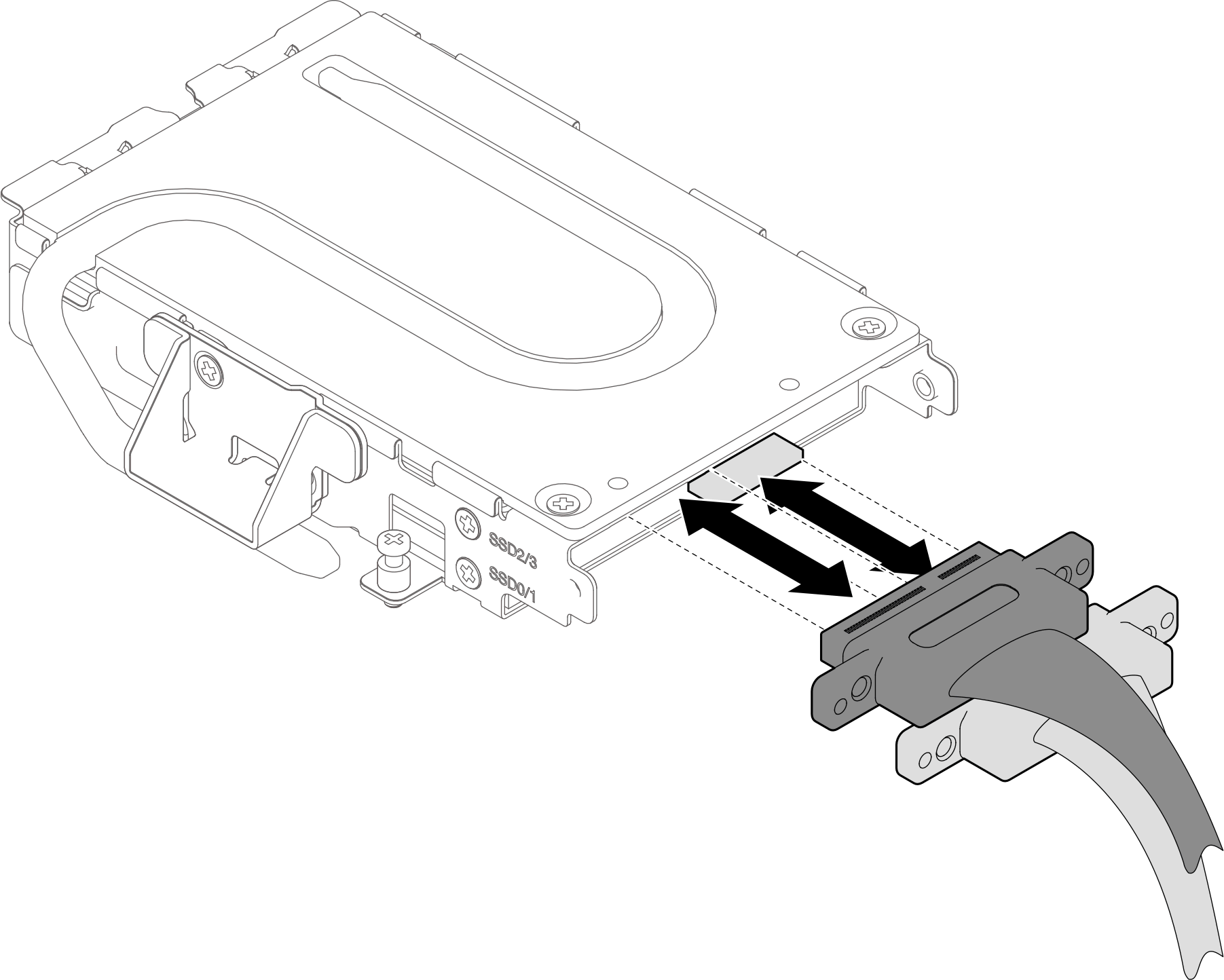
- Install the cable retainer to the drive cage.
- Attach the cable retainer to the drive cage. Cable retainer orientation is different for top-side cooling drive and bottom-side cooling drive. Make sure to follow the cable retainer orientation guidance specified in the illustrations below.Attention
For top-side cooling drive, orient the cable retainer as 1 shown in the illustration below.
For bottom-side cooling drive, orient the cable retainer as 2 shown in the illustration below.
Figure 13. Installing cable retainer to the drive cage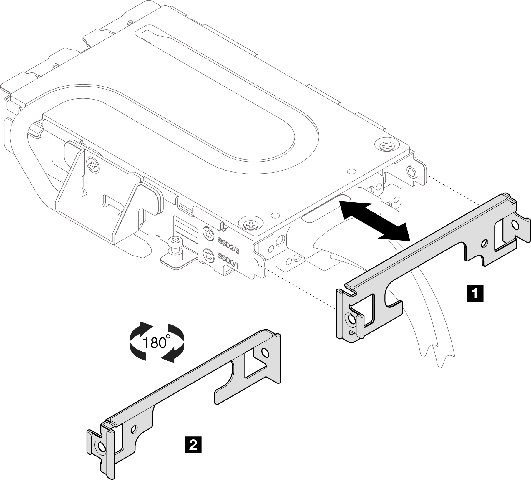
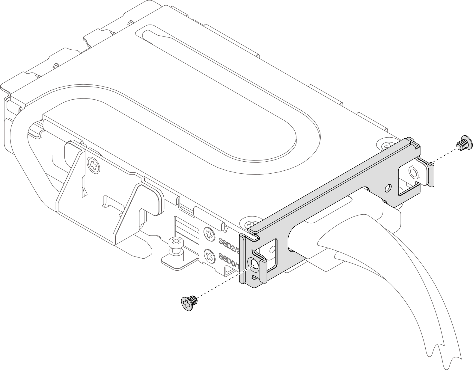
- Fasten two PH 1 screws to secure the cable retainer to the drive cage.Figure 14. Installing cable retainer to the drive cage
- Attach the cable retainer to the drive cage. Cable retainer orientation is different for top-side cooling drive and bottom-side cooling drive. Make sure to follow the cable retainer orientation guidance specified in the illustrations below.
Install the front E3.S drive cage. See Install an E3.S front drive cage assembly.
Install the cross braces. See Install the cross braces.
Install the tray cover. See Install the tray cover.
Install the tray into the enclosure. See Install a tray in the enclosure.
- Connect all required external cables to the solution.NoteUse extra force to connect QSFP cables to the solution.
- Check the power LED on each node to make sure it changes from fast blink to slow blink to indicate all nodes are ready to be powered on.Note
Shared I/O configuration requires specific nodes power-on sequence. When powering on the system, power on Node B first; then, power on Node A. For more information, see PCIe adapter cable routing.