Install the processor board
Use this information to install the processor board.
About this task
Screwdriver for M3 PH1, PH 1, PH 2, T10, and T30 screws
Waterloop Service Kit (SC750 V4) (The water loop carrier in the Service Kit is reusable, it is recommended to keep it at the facility where the server operates for future replacement needs.)
Up VR Gap Pad Kit (SC750 V4)
Down VR Gap Pad Kit (SC750 V4)
MID E3.S TOP Gap Pad (SC750 V4) , if E3.S middle drive is installed.
MID E3.S BOT Gap Pad (SC750 V4) , if E3.S middle drive is installed.
Storage Gap Pad Kit (SC750 V4) , if E3.S front drive is installed.
Storage Gap Pad Kit (SC750 V4) , if E3.S 1T dual front drives or E3.S 2T single front drive are installed.
CX7 NDR200 Gap Pad (SC750 V4) , if ConnectX-7 NDR 200 adapter is installed.
CX7 Gap Pad (SC750 V4) , if ConnectX-7 NDR 400 adapter is installed.
For gap pad location and instruction, see Gap pad identification and location.
Before replacing the gap pad, gently clean the surface with an alcohol cleaning pad.
Hold the gap pad carefully to avoid deformation. Make sure no screw hole or opening is blocked by the gap pad material.
Read Installation Guidelines and Safety inspection checklist to ensure that you work safely.
Turn off the corresponding DWC tray that you are going to perform the task on.
Disconnect all external cables from the enclosure.
Use extra force to disconnect QSFP cables if they are connected to the solution.
To avoid damaging the water loop, always use the water loop carrier when removing, installing or folding the water loop.
Go to Drivers and Software download website for ThinkSystem SC750 V4 to see the latest firmware and driver updates for your server.
Go to Update the firmware for more information on firmware updating tools.
- A video of this procedure is available at YouTube.
Procedure
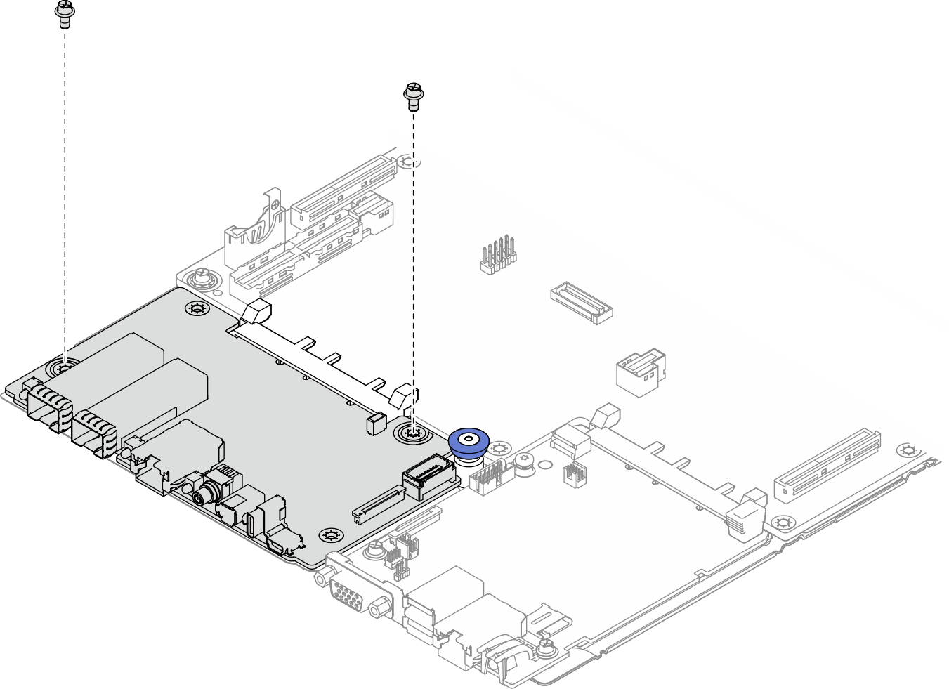
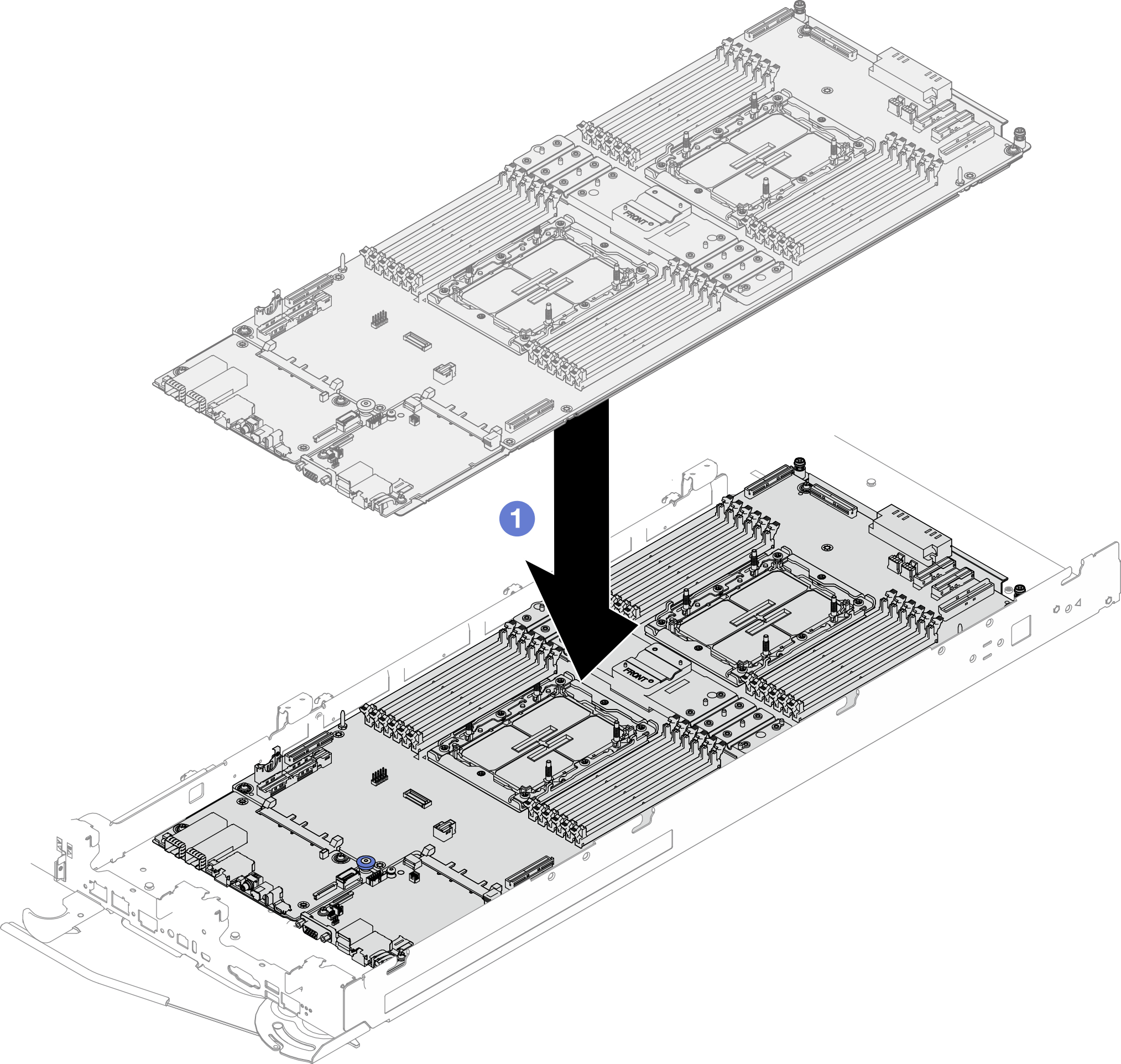
- Install the processor board.
 Align the processor board with three guide flanges on the supporting metal sheet; then, install the processor board.
 Install three Phillips #1 screws per node on the processor board (with a torque screwdriver set to the proper torque).
NoteFor reference, the torque required for the screws to be fully tightened/removed is 0.5-0.6 newton-meters, 4.5-5.5 inch-pounds.
Figure 1. Processor board installation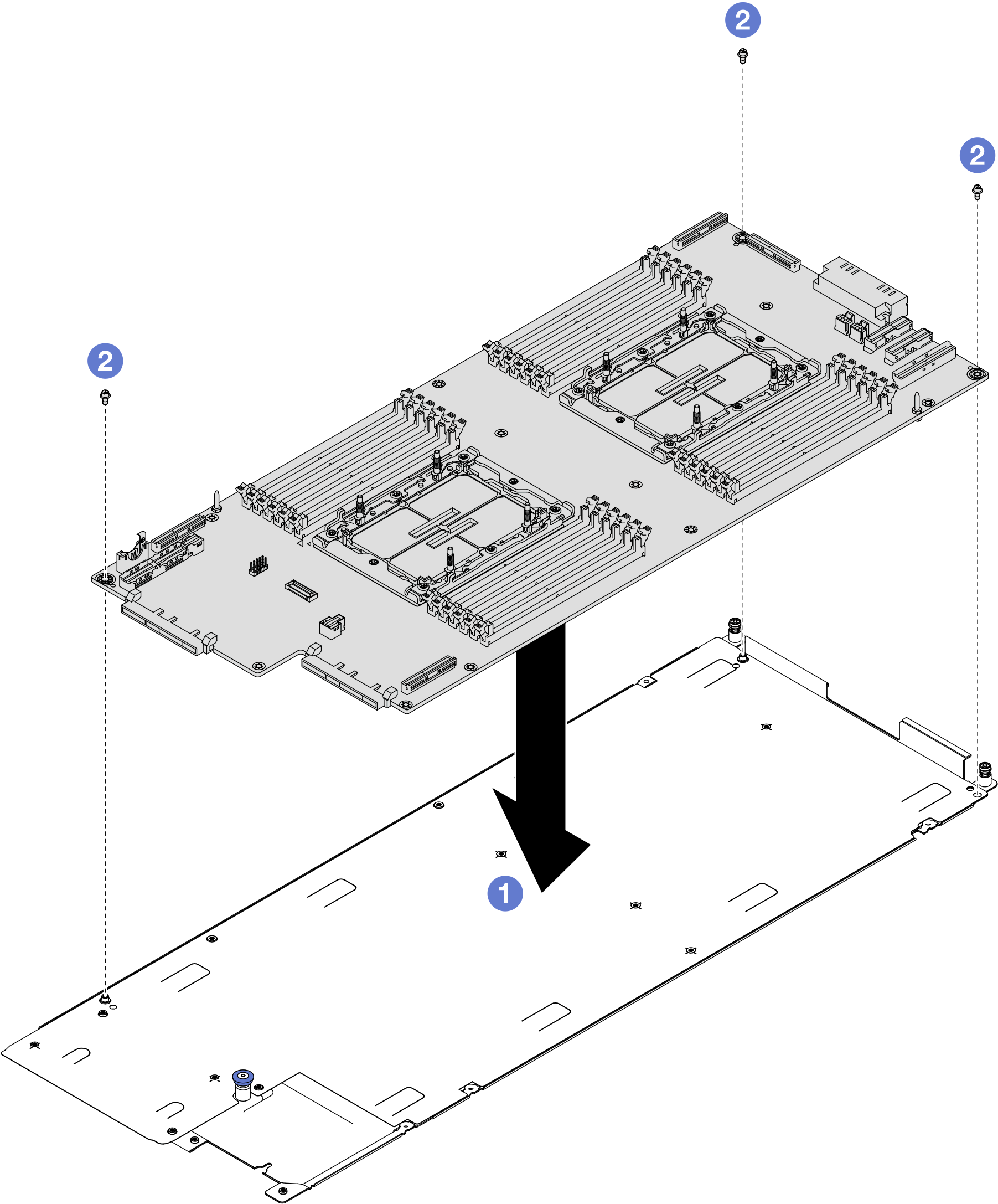
- Check the gap pads on the top side of the VR cold plate, if any of them are damaged or detached, replace them with new ones.NoteMake sure to follow
Gap pad replacement guidelines. Figure 2. VR cold plate top side gap pads locations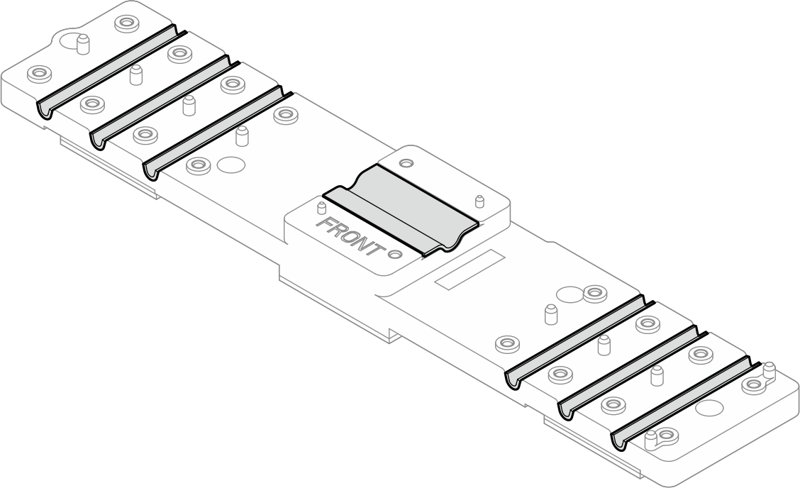
- Replace the single-use gap pads on bottom side of the VR cold plate with new ones.NoteMake sure to follow
Gap pad replacement guidelines. Figure 3. VR cold plate bottom side single use gap pads locations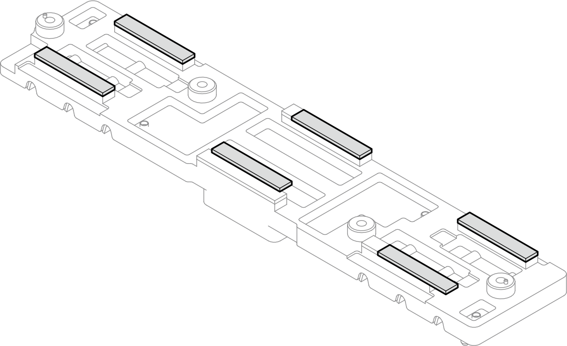
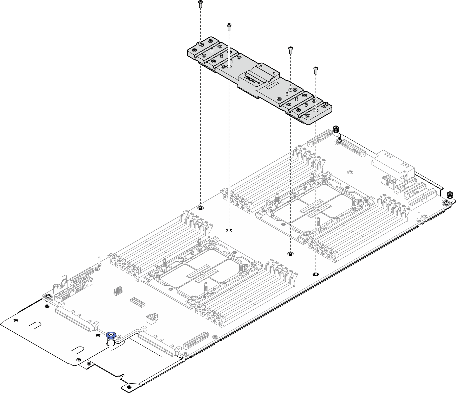
- Install the four Torx T10 screws (per node) to install the VR cold plate to the processor board.Figure 4. Installing VR cold plate
- Install the system I/O board.
- Install the system I/O board to the system board assembly.
- Install two M3 PH1 screws to secure the system I/O board to the system board assembly.
Figure 5. Installing the system I/O board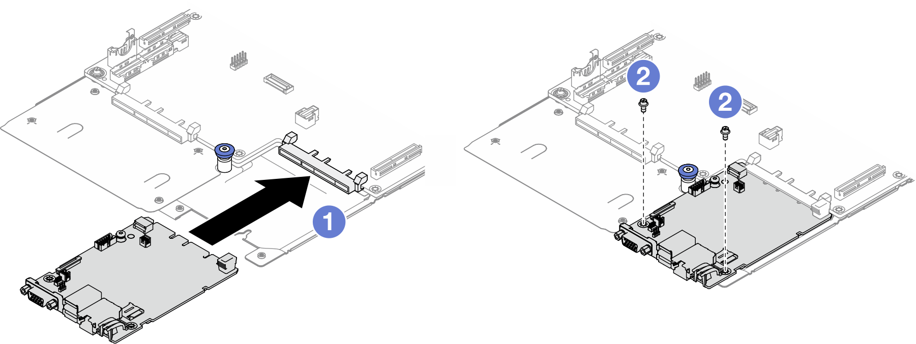
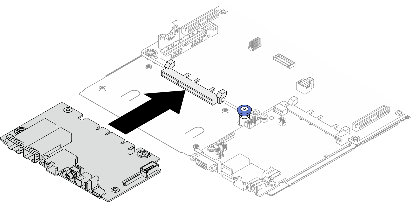
- Install the front I/O board to the system board assembly.Figure 6. Installing the front I/O board
- There is a Mylar sheet between the front I/O board and the supporting metal sheet. Figure 7. Side view of front I/O board portion of the system-board assembly
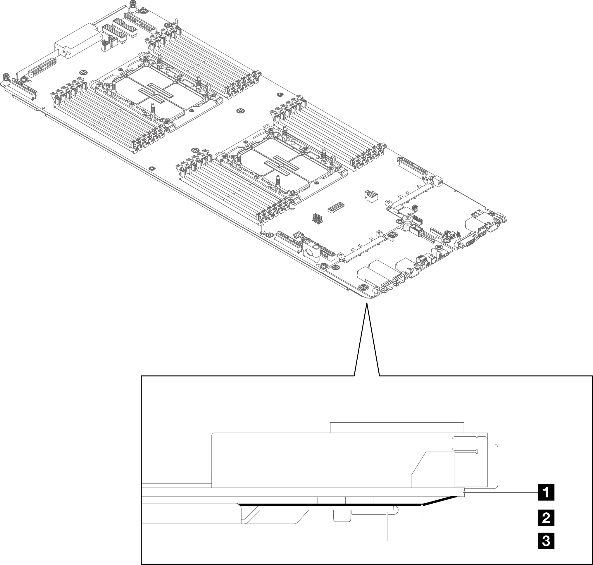
1 Front I/O board 2 Mylar sheet 3 Supporting sheet metal - Insert the tip of the DIMM tool between the front I/O board and the Mylar sheet. Then, use the tip to press down the Mylar sheet to prevent the dip pins on the bottom of the FIO board sticking to the Mylar sheet.Figure 8. Separating Mylar sheet from front I/O board
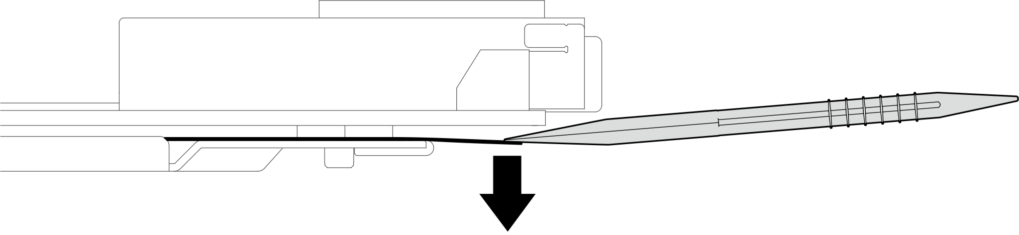
- Insert the tip of the DIMM tool between the front I/O board and the Mylar sheet. Then, use the tip to press down the Mylar sheet to prevent the dip pins on the bottom of the FIO board sticking to the Mylar sheet.
- Install two M3 PH1 screws to secure the front I/O board to the system board assembly.Figure 9. Installing front I/O board screws
- Install the FPC cable to the front I/O board and the system I/O board.
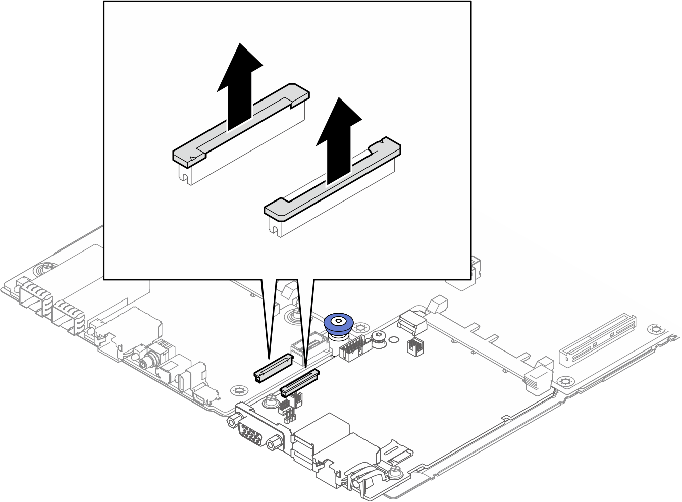
- Pull up the latch of the connectors on the front I/O board and the system I/O board.Figure 10. Pulling up connector latches
- Match the silkscreen on the FPC cable and the connectors. Then, install the FPC cable to the front I/O board and the system I/O board.
FPC cable connection to FIO board and system I/O board From To FPC cable end marked as FIO SIDE → FIO SIDE connector on Front I/O board FPC cable end marked as SCM SIDE → PHY CONN connector on system I/O board Figure 11. FPC cable connection
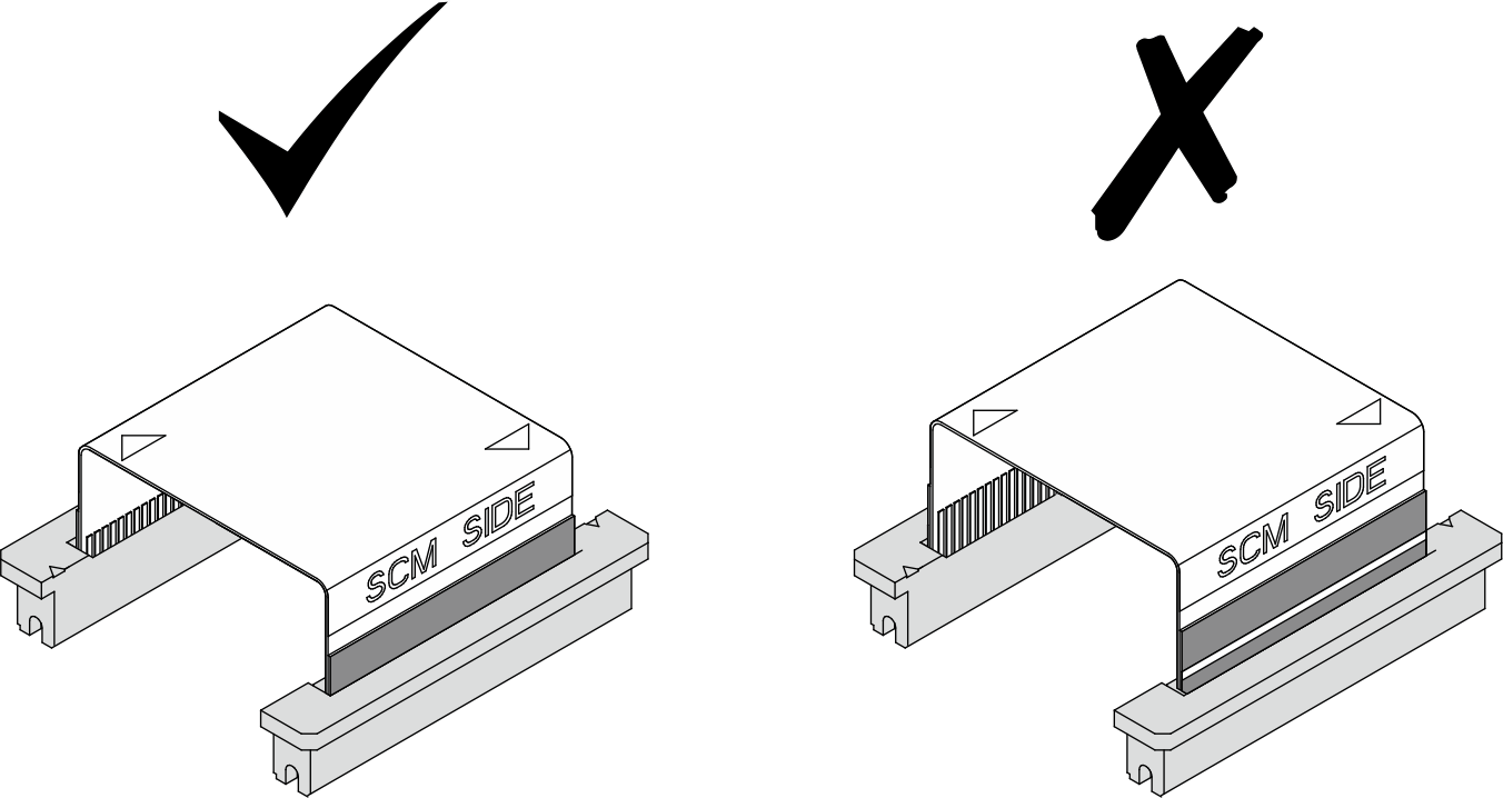
- There is a white line on both ends of the FPC cable. Insert the FPC cable to the connectors until the white lines are invisible. The FPC cable is not installed correctly if the white lines are visible.Figure 12. Checking proper FPC cable installation
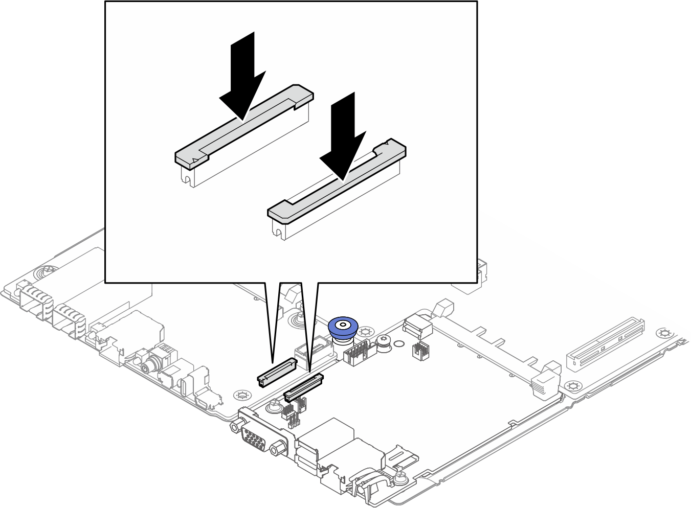
 If the white line is still visible after inserting the FPC cable, check if the connector latches are fully pulled up and loosen.Figure 13. Pulling up connector latches
 - Press the latches to secure the FPC cable to the connectors.Figure 14. Pressing connector latches
- Pull up the latch of the connectors on the front I/O board and the system I/O board.
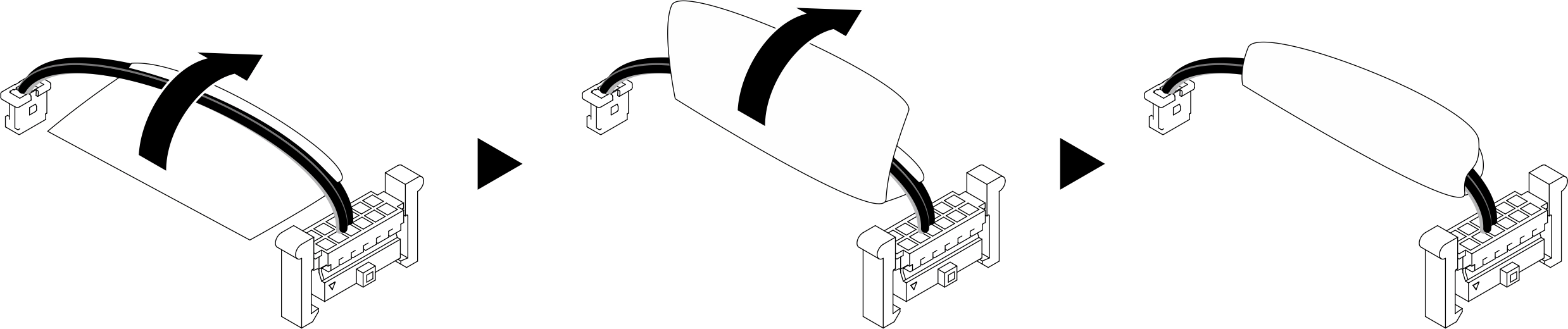
- A label is attached to the COM port cable. Roll the label around the cable all the way through to prevent label interfering with system connectors and water loop.Figure 15. Rolling label around the COM port cable
- Install the COM port cable to the front I/O board and system I/O board. Place the cable between plunger and serial log connector.
1 Serial log connector on front I/O board 2 COM port connector on system I/O board Figure 16. Removing COM port cable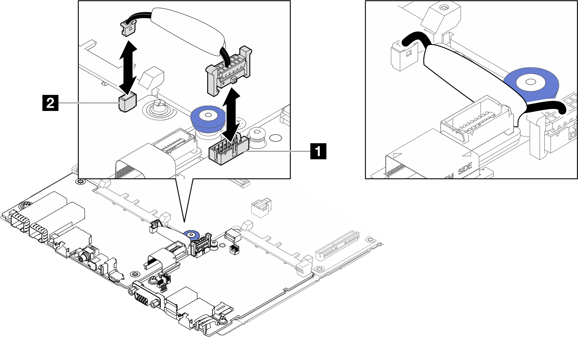 AttentionThe COM port cable should be placed between the plunger and the serial log connector.Figure 17. Top view of COM port cable routing
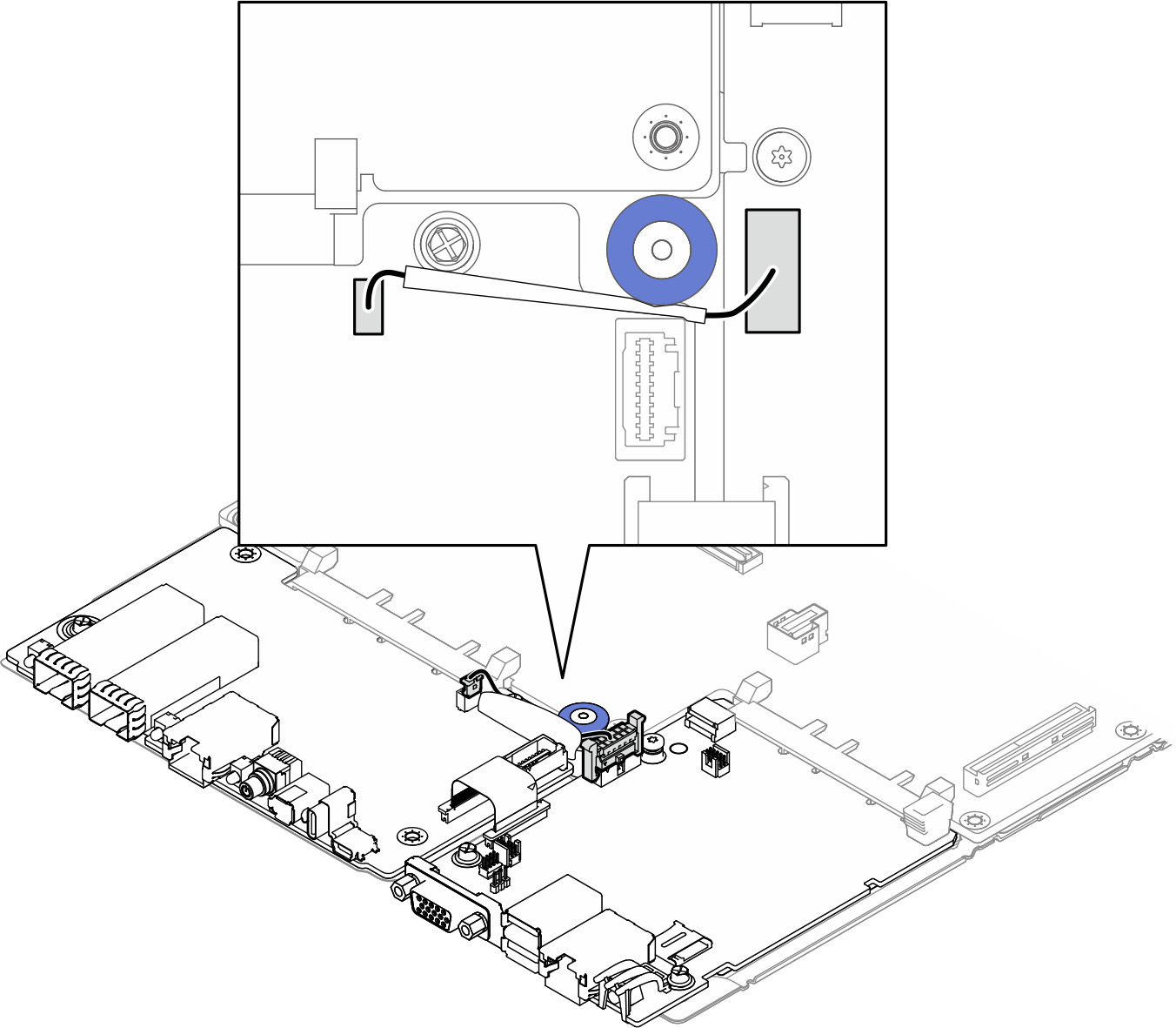
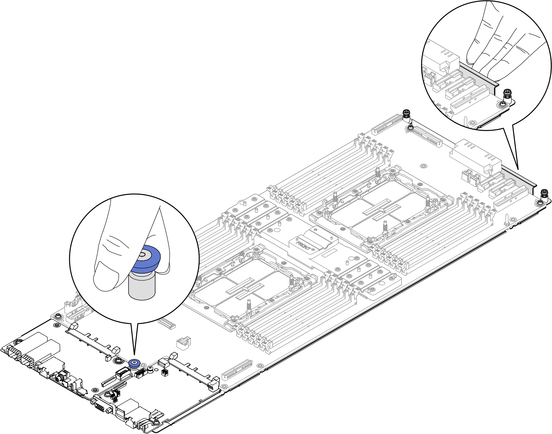
- Install the system-board assembly to the tray.NoteHold the system-board assembly by the thumbscrew in the front and the tab beside the power connector.Figure 18. Holding the system-board assembly
- Place the system board assembly into the tray.Figure 19. Installing the system-board assembly
- Press the SFP Ethernet ports on the FIO board.
 While pressing the SFP Ethernet ports, slide the system board assembly forward to secure the front connectors in the corresponding openings on the front bezel.
Figure 20. Securing the system board assembly to the tray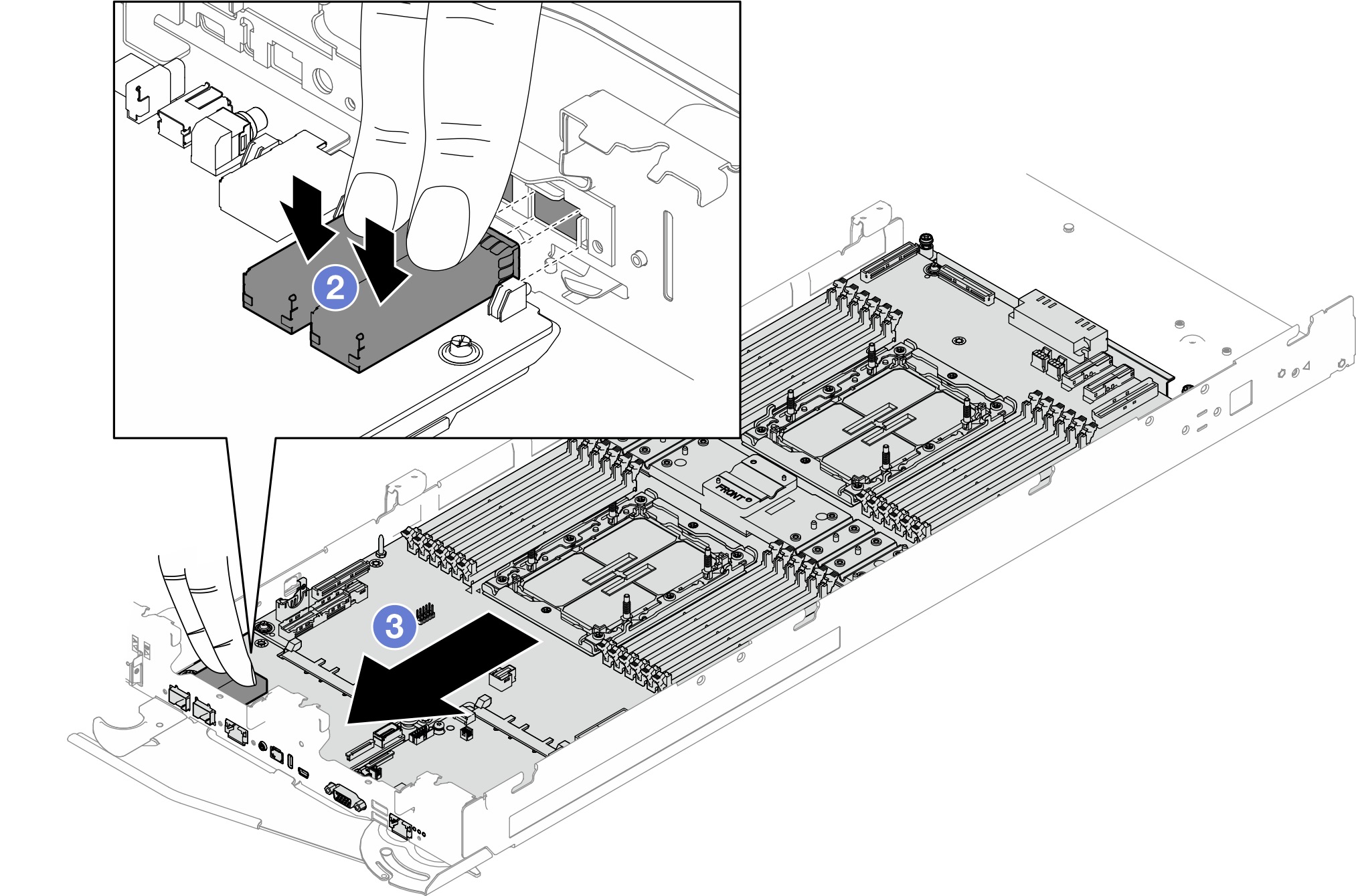
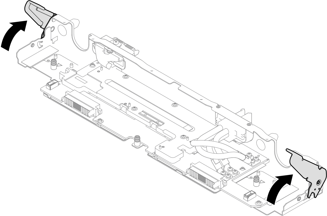
- Make sure the PDB tray handles are rotate to unlock position.Figure 21. PDB tray handle unlock position
- Install the PDB tray.
- Align the power connectors on PDB tray to the power connectors to the system boards.
- There are triangle markings on the inside of the right-side and left-side of the tray. Push the PDB tray into the server tray. Stop pushing when the PDB tray meets the triangle markings.
- Rotate both PDB tray handles at the same time to the lock position
AttentionMake sure to rotate both handles at the same time.Figure 22. Installing the PDB tray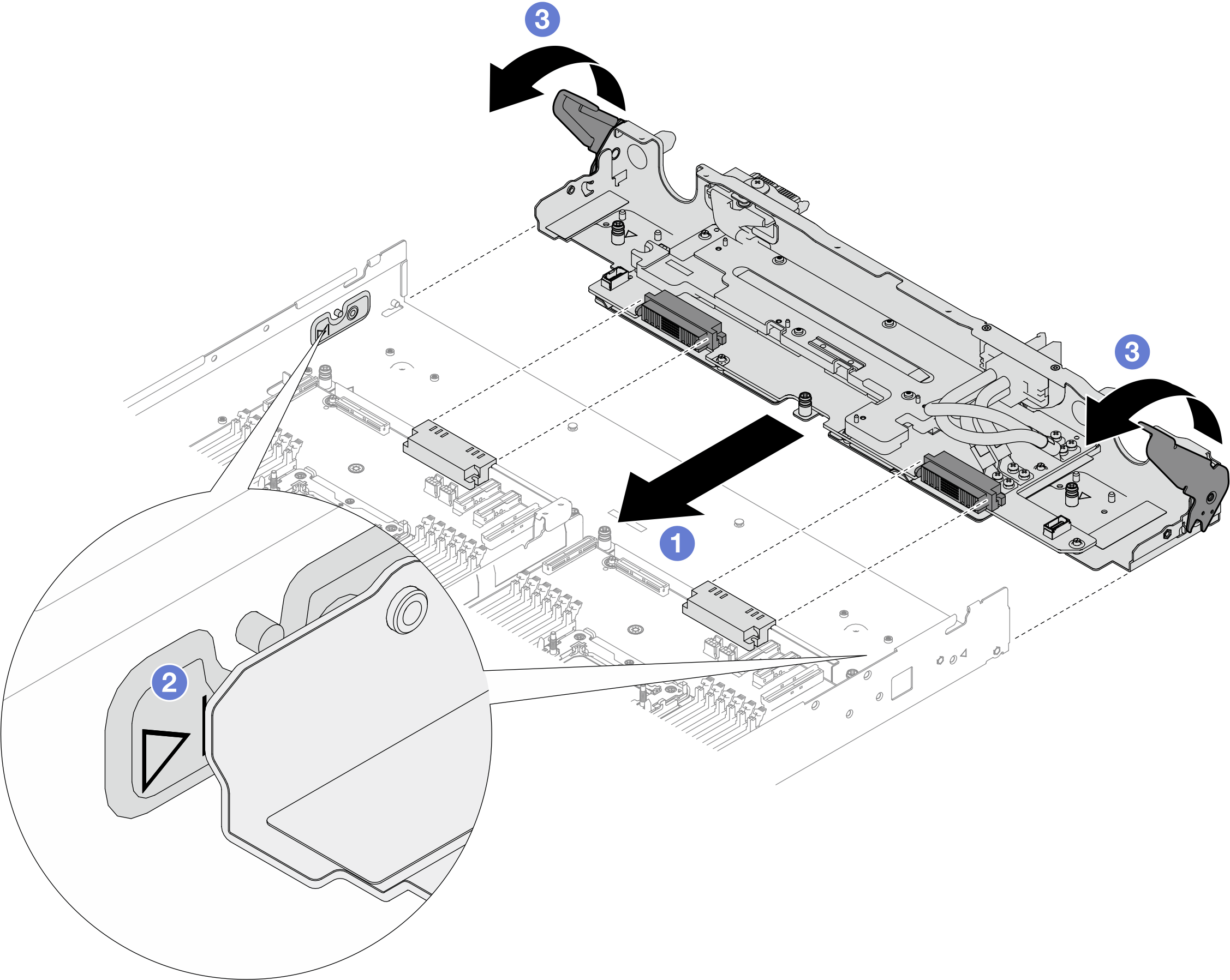
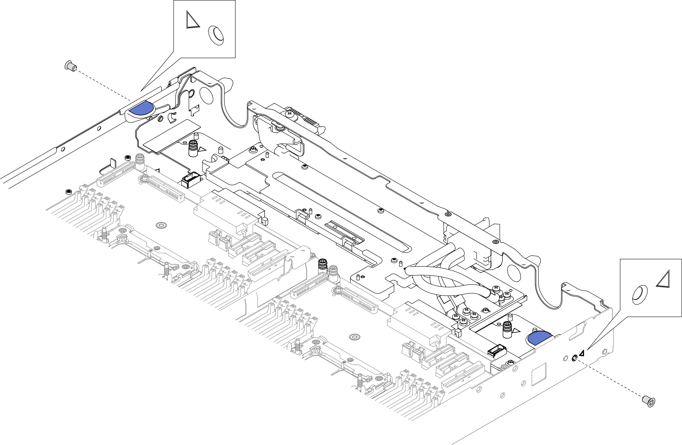
- Install two PH1 screws from the outside of the tray.Figure 23. Installing screws from the outside of the tray.
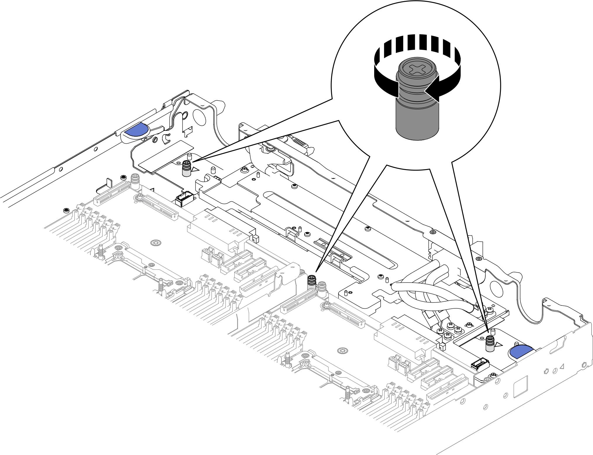
- Fasten the three PH1 captive screws to install the PDB tray to the server tray.Figure 24. Fastening captive screws
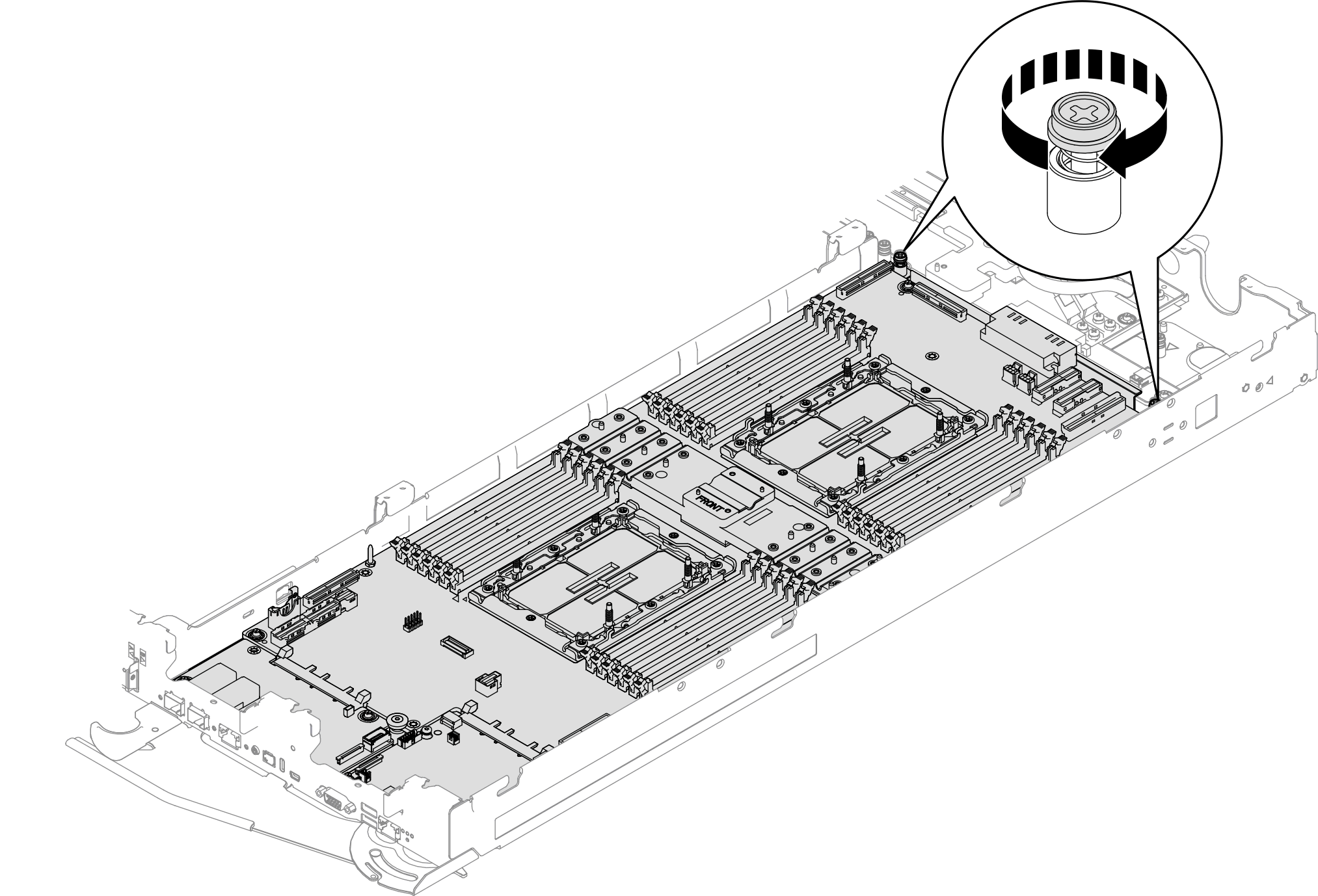
- Fasten two PH1 captive screws to secure the system-board assembly to the tray.Figure 25. Fastening captive screws on system-board assembly
Install the water loop. See Install the water loop.
(Optional) When installing processor board to Node A, install the leakage sensor holder. Place the leakage sensor holder to the tray, and install two screws to secure it to the tray.
Figure 26. Installing leakage sensor holder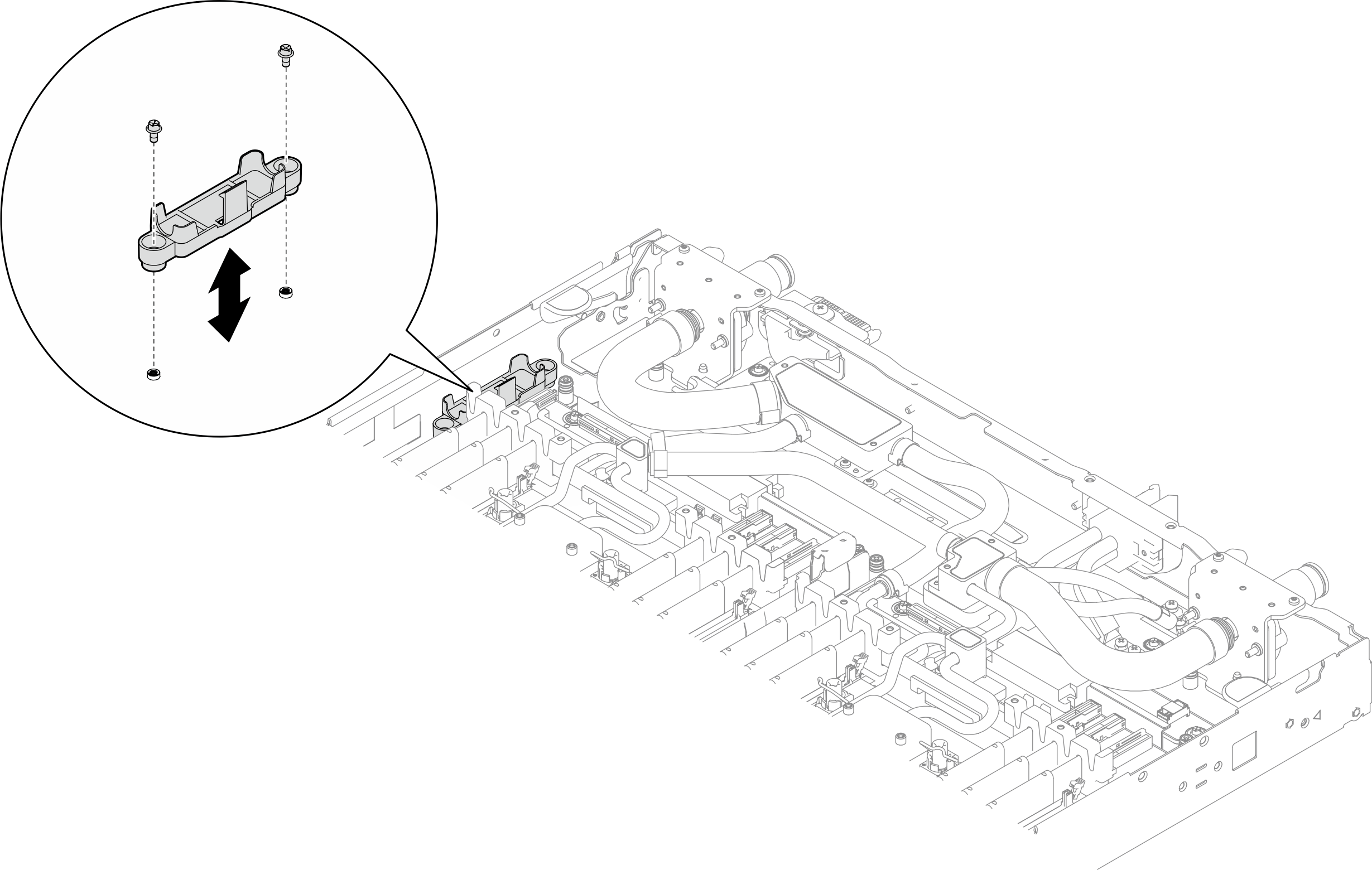
Install the leakage sensor. See Install the leakage sensor.
Install the sideband cable kit. See Install the system management sideband cable kit.
Install the middle E3.S drive cage. See Install an E3.S 1T middle drive cage assembly.
- Install the PCIe adapter riser cage. See Install a ConnectX-7 NDR 200 adapter riser assembly or Install a ConnectX-7 NDR 400 adapter riser assembly.
Install the front E3.S drive cage. See Install an E3.S front drive cage assembly.
If the system will be installed with memory modules that requires dual-side cooling, install DIMM cooling bars. See Install a DIMM cooling bar.
Install the cross braces. See Install the cross braces.
Install the memory module, perform one of the following.
Install the memory modules that require single-side cooling. See Install a memory module (single-side cooling)., or
Install the memory modules that require dual-side cooling. See Install a memory module (dual-side cooling).
Install the DIMM comb. See Install a DIMM comb.
Install the tray cover. See Install the tray cover.
Install the tray into the enclosure. See Install a tray in the enclosure.
- Connect all required external cables to the solution.NoteUse extra force to connect QSFP cables to the solution.
- Check the power LED on each node to make sure it changes from fast blink to slow blink to indicate all nodes are ready to be powered on.Note
Shared I/O configuration requires specific nodes power-on sequence. When powering on the system, power on Node B first; then, power on Node A. For more information, see PCIe adapter cable routing.
Update the vital product data (VPD). See Update the Vital Product Data (VPD).
Machine type number and serial number can be found on the ID label, see Identify the solution and access the Lenovo XClarity Controller.