Install a ConnectX-8 adapter riser assembly
Use this information to install a ConnectX-8 adapter riser assembly.
About this task
Screwdriver for T6 and PH1 screws
Waterloop Miscellaneous Kit (SC750 V4) .
CX8 Conduction Plate
CX8 Gap Pad (if installing ConnectX-8 for the first time)
The system supports two types of riser cages, 1 with A/B printing and 2 with A/B/C/D printing, as shown in the illustration below. Make sure to use riser cage 2 when installing the Connect-X 8 adapter.
Figure 1. Riser cage types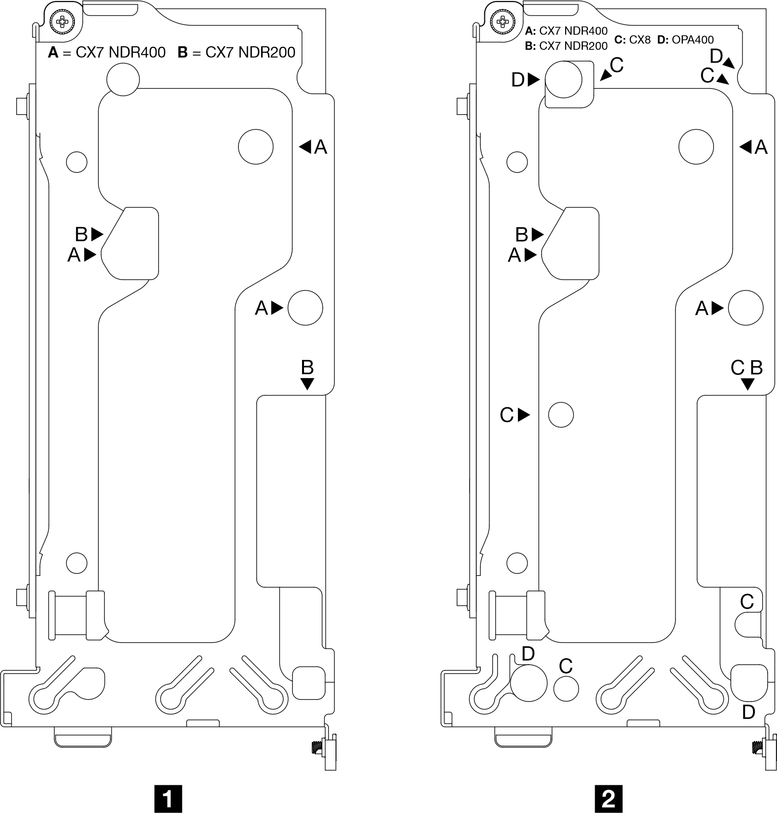
The system supports two types of front cross bars, as 1 and 2 shown in the illustration below, with the triangle marks pointing out their differences. Make sure to use front cross bar 2 if the system operates the Connect-X 8 shared I/O configuration or Connect-X 8 socket direct configuration.
Figure 2. Front cross bar types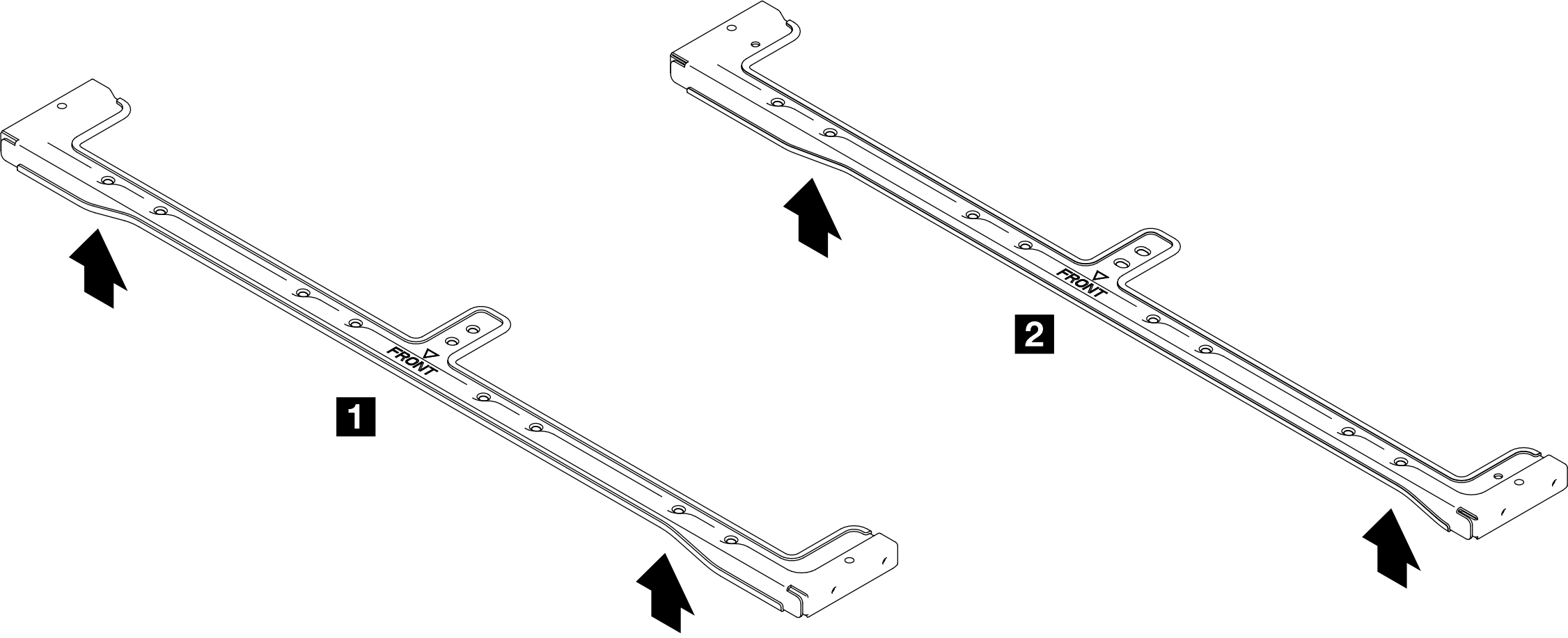
For gap pad location and instruction, see Gap pad identification and location.
Before replacing the gap pad, gently clean the surface with an alcohol cleaning pad.
Hold the gap pad carefully to avoid deformation. Make sure no screw hole or opening is blocked by the gap pad material.
Read Installation Guidelines and Safety inspection checklist to ensure that you work safely.
Turn off the corresponding DWC tray that you are going to perform the task on.
Disconnect all external cables from the enclosure.
Use extra force to disconnect QSFP cables if they are connected to the solution.
- A video of this procedure is available at YouTube.
Procedure
- Make sure to install correct type of PCIe riser cage to the corresponding riser slot.NoteThe type of PCIe riser cage installed in slot 1 and slot 2 are different. See the illustration below for proper PCIe riser cage installation.
Riser cage type Slot numbering 1 Riser cage with cabled riser PCIe slot 2 2 Standard riser cage PCIe Slot 1 Figure 3. PCIe riser cage types for slot 1 and slot 2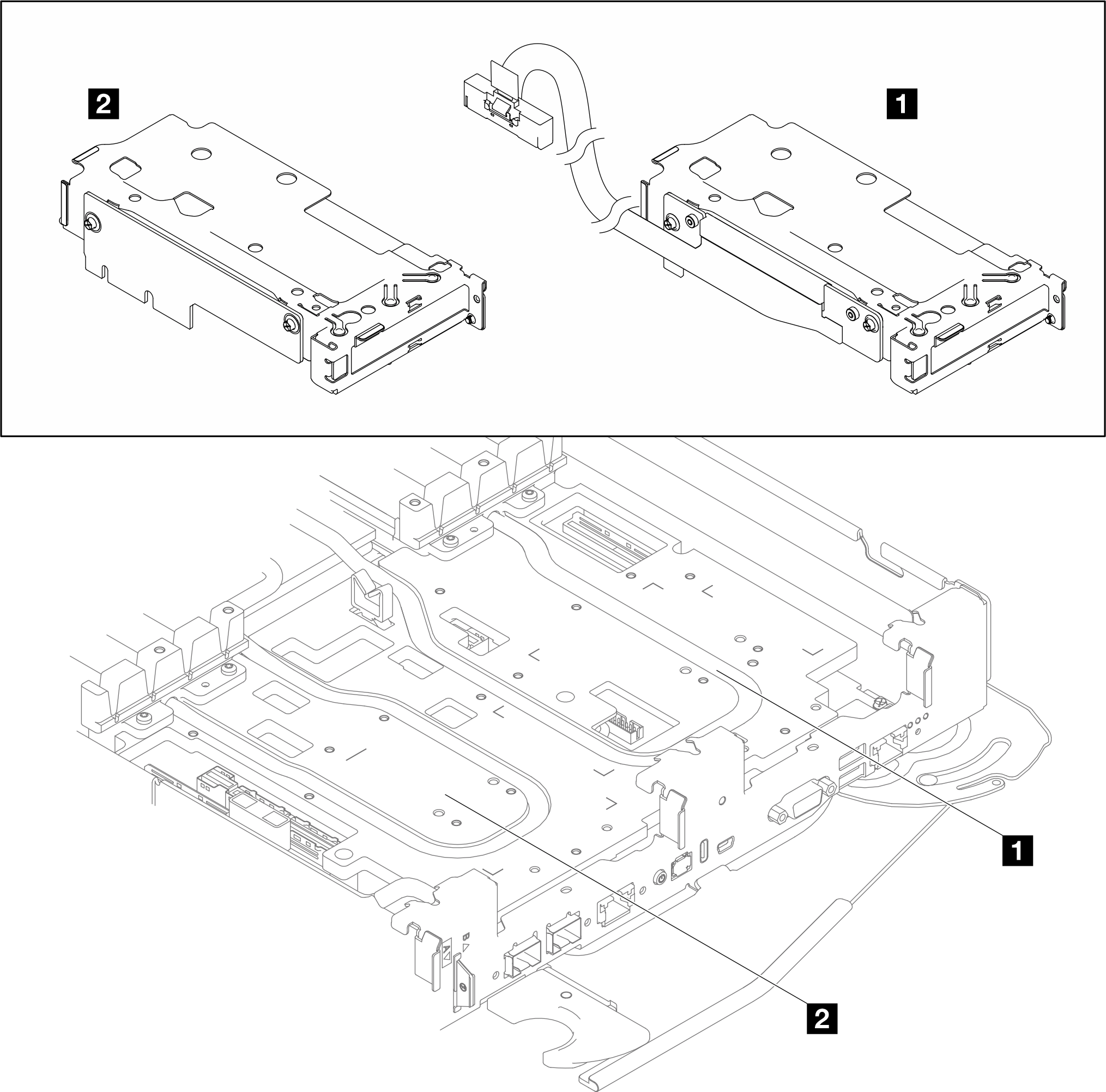
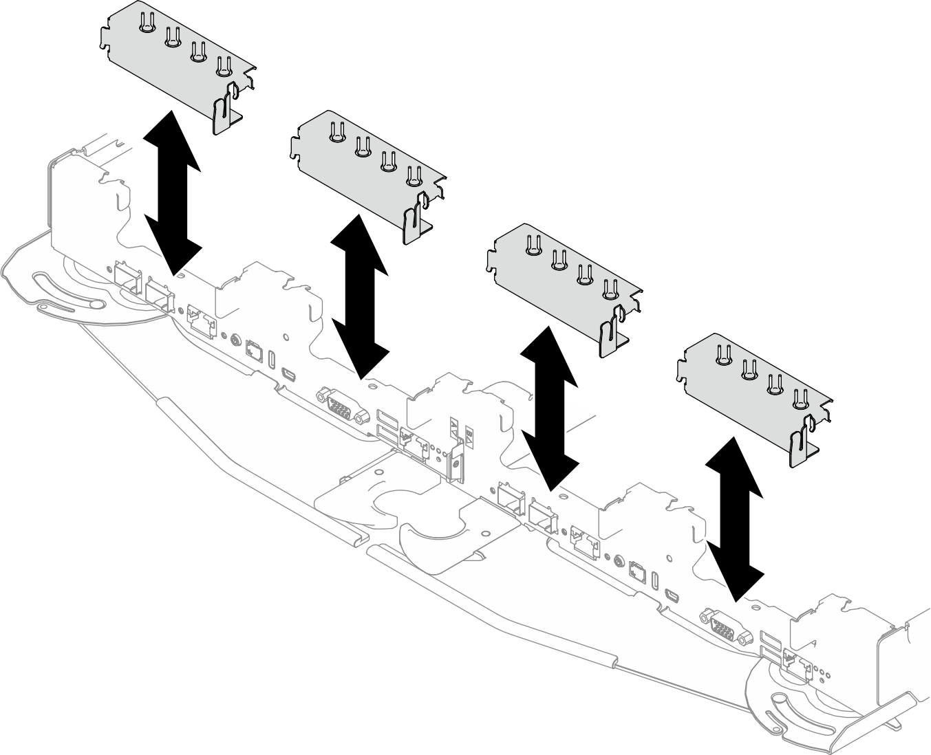
- Remove the blank bezel fillers if they are installed.Figure 4. Removing blank bezel filler
- If the interface plate was removed, install the interface plate to the water loop.
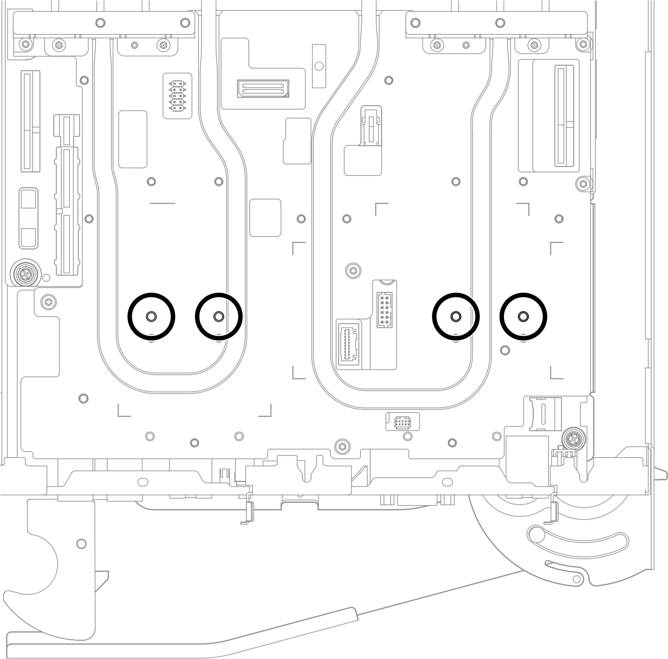
- Align the interface plate with the two guide pins on the water loop (marked with circles in the illustration below).Figure 5. Guide pins for PCIe adapter interface plate
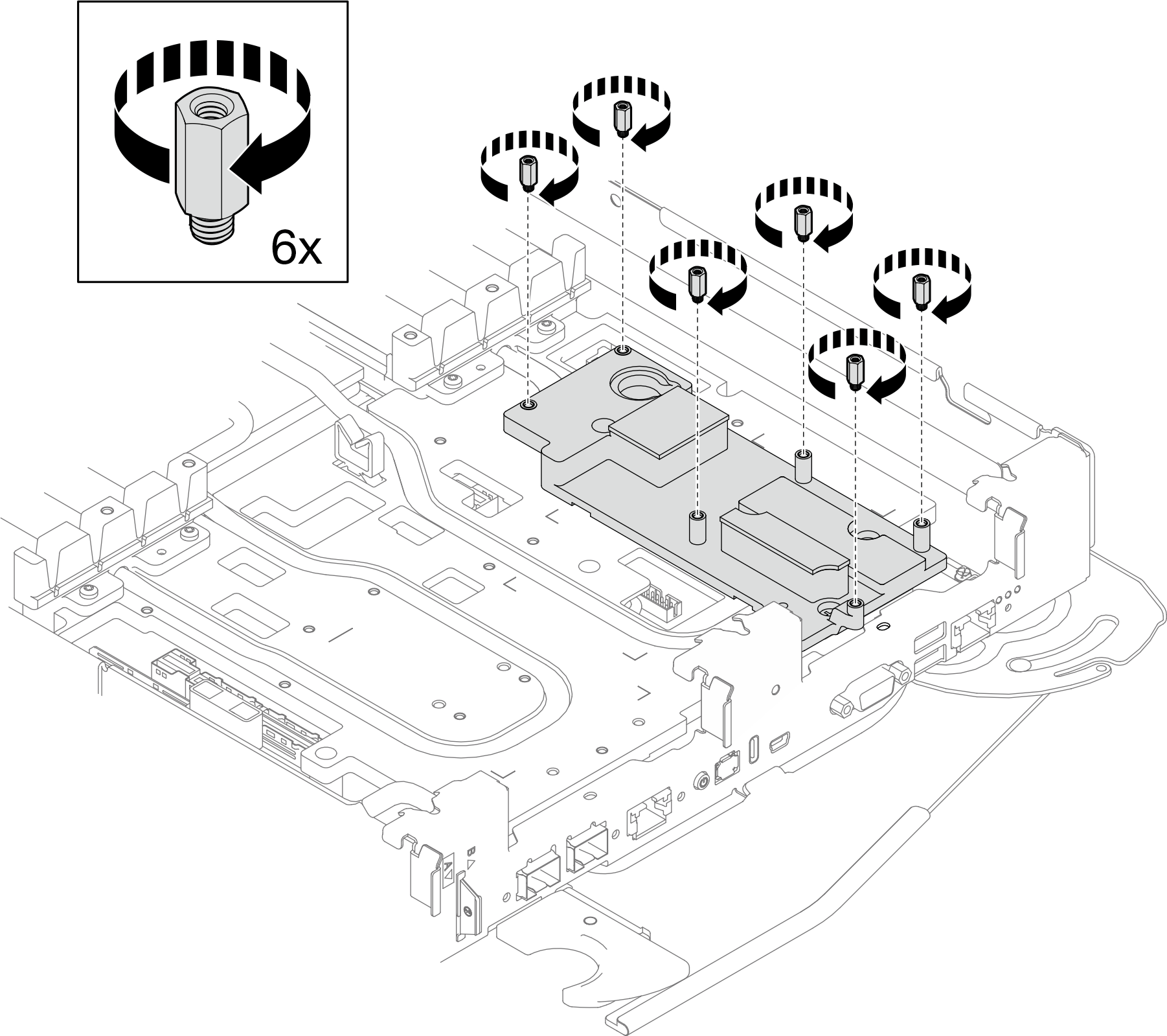
- The interface plate must be installed with six studs. If not, install the six studs to the interface plate.Figure 6. Installing six studs to the interface plate
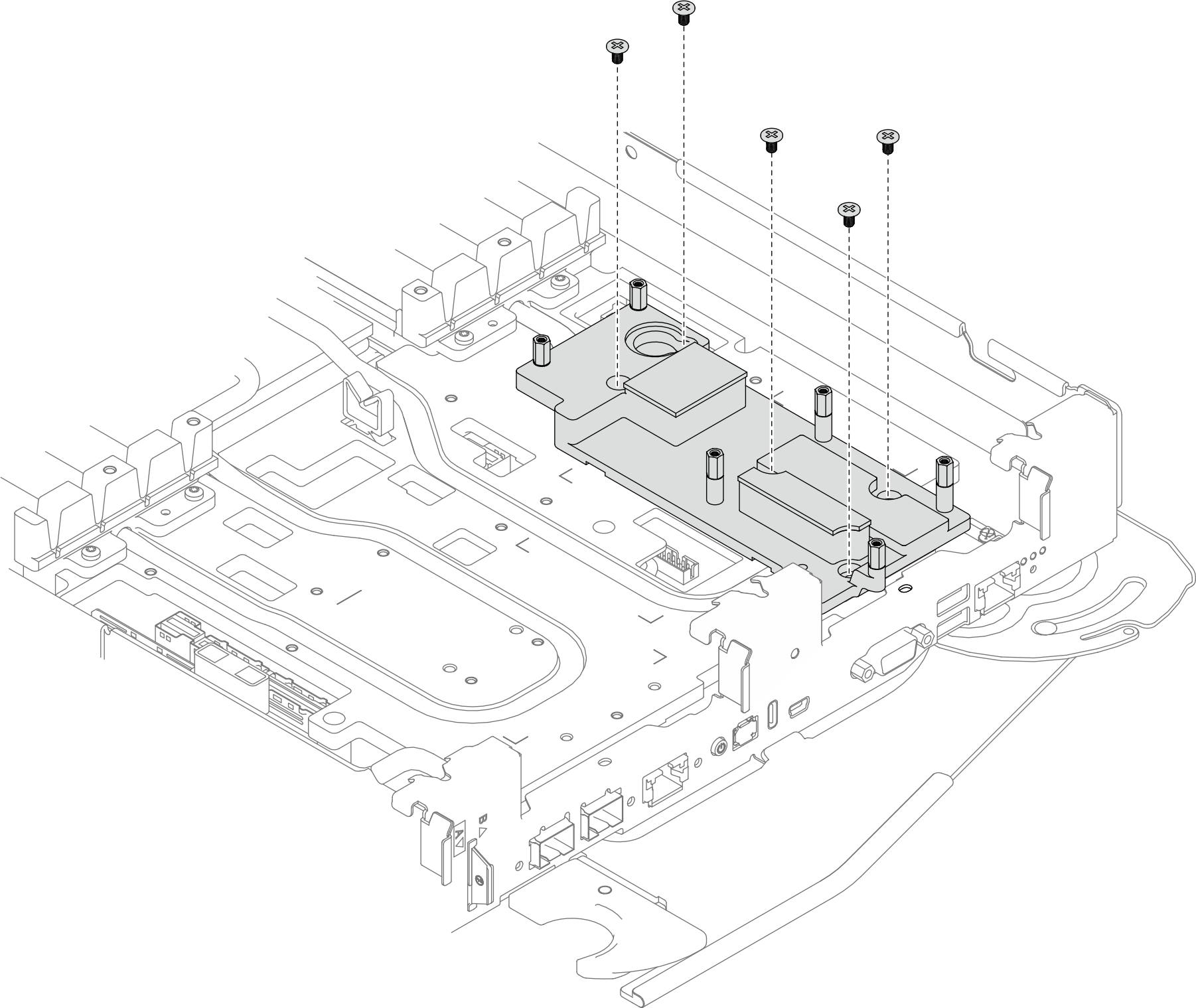
- Place the interface plate on the water loop; then, install five PH1 screws.Figure 7. ConnectX-8 riser assembly interface plate installation
- Align the interface plate with the two guide pins on the water loop (marked with circles in the illustration below).
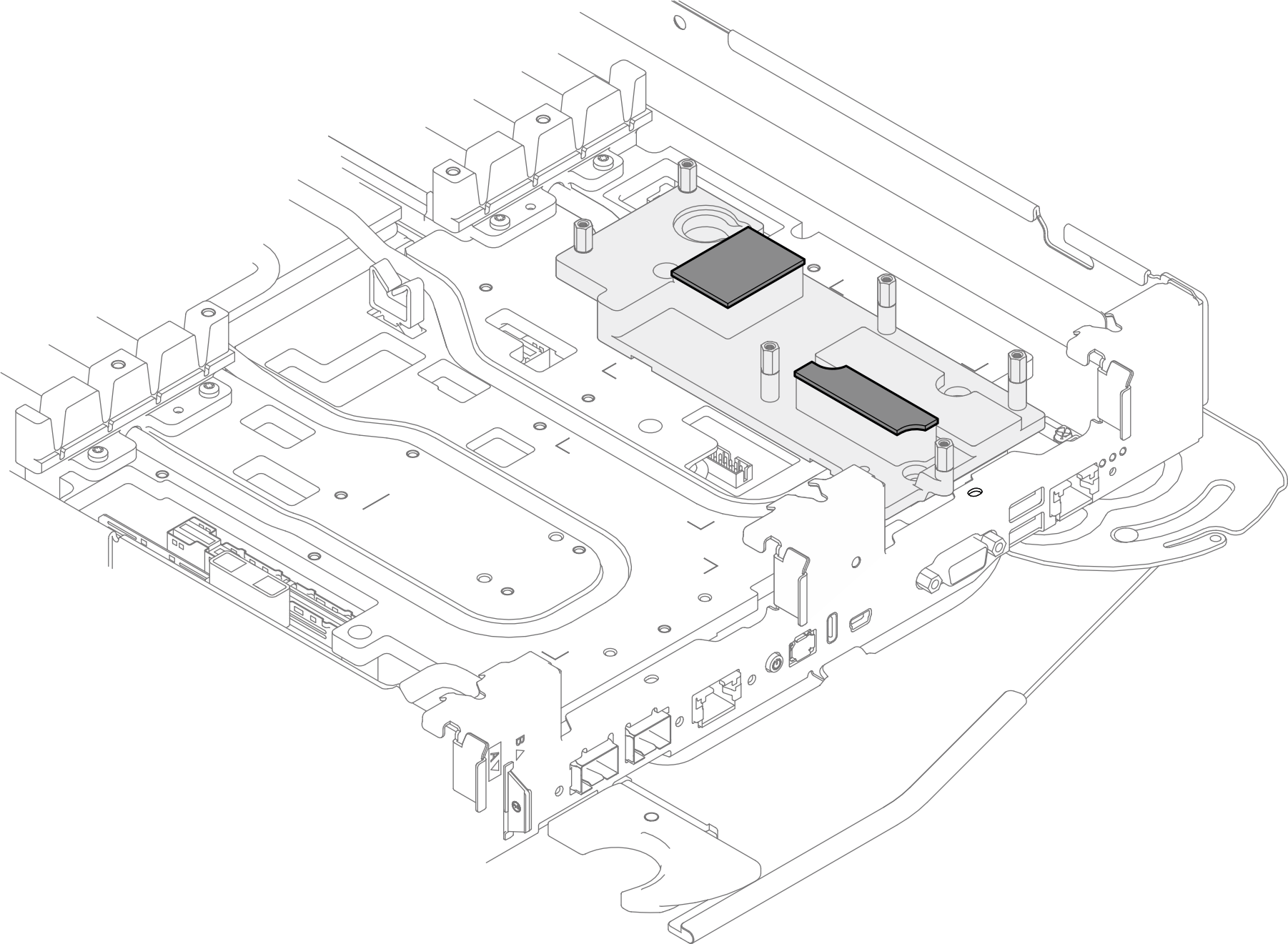
- Replace the single-use gap pad on the interface plate with a new one. Make sure to follow Gap pad/putty pad replacement guidelines.Figure 8. ConnectX-8 riser assembly interface plate single-use gap pad
- Install the ConnectX-8 riser assembly.
 Install the ConnectX-8 riser assembly to the water loop.
 Install six T6 screws to screw holes marked with C on the riser cage. Install the screws with a torque screwdriver set to the proper torque.
 Fasten the captive screw to secure the riser assembly to the water loop.
NoteFor reference, the torque required for the screws to be fully tightened/removed is 3+/- 0.5 lbf-in.
Figure 9. Installing ConnectX-8 riser assembly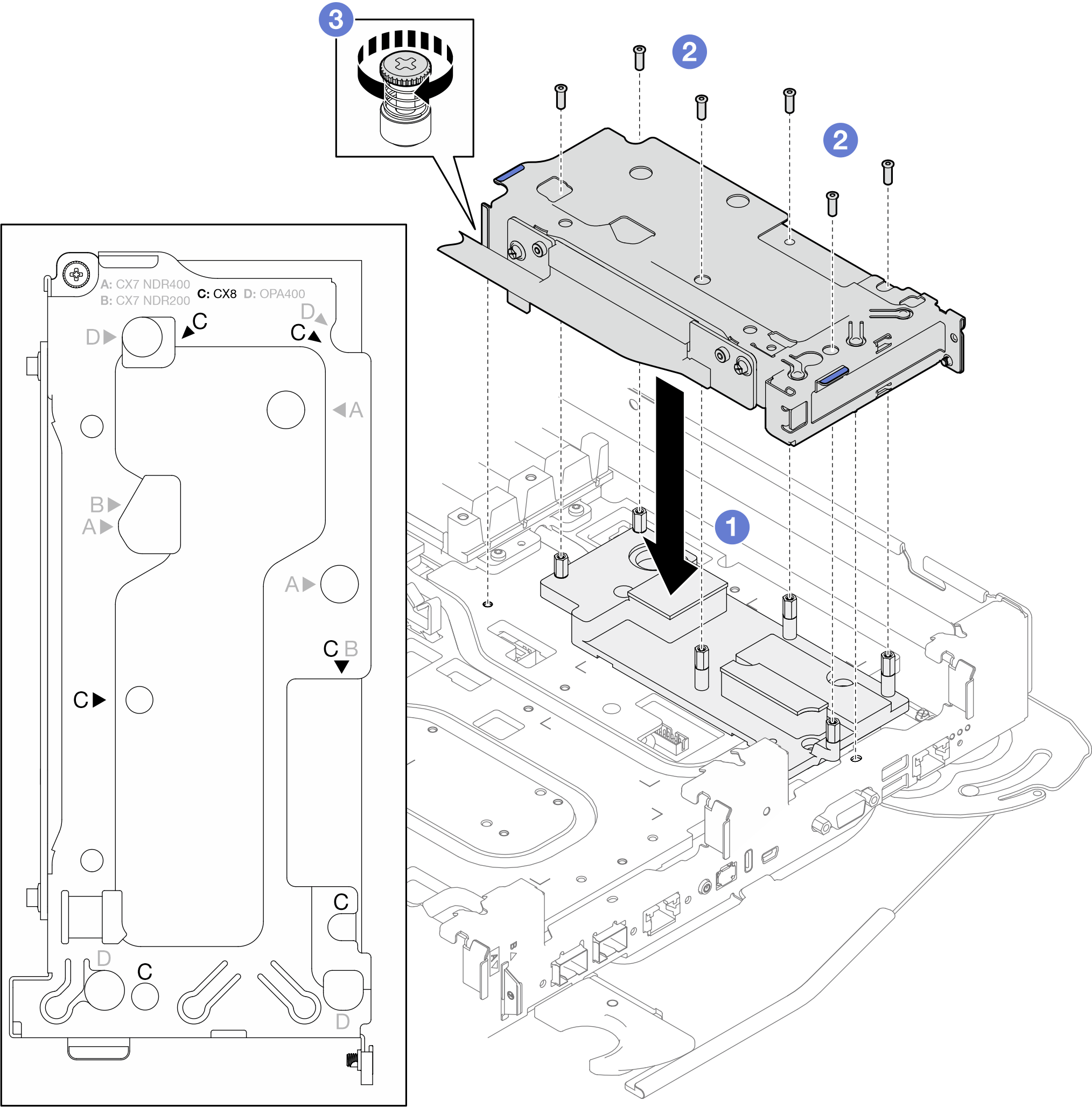 Figure 10. Screw holes marked with C on the riser cage
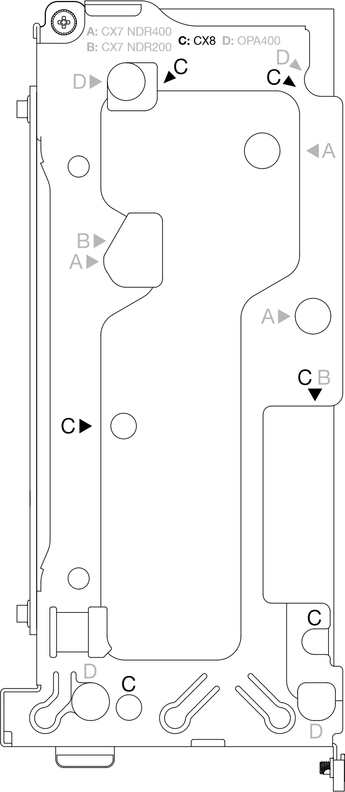
Connect the PCIe adapter cables to the system board. See Internal cable routing.
Install the cross braces. See Install the cross braces.
Install the tray cover. See Install the tray cover.
Install the tray into the enclosure. See Install a tray in the enclosure.
- Connect all required external cables to the solution.NoteUse extra force to connect QSFP cables to the solution.
- Check the power LED on each node to make sure it changes from fast blink to slow blink to indicate all nodes are ready to be powered on.Note
Shared I/O configuration requires specific nodes power-on sequence. When powering on the system, power on Node B first; then, power on Node A. For more information, see PCIe adapter cable routing.