Front drive and PCIe adapter configuration
This section contains information on the front drive and PCIe adapter configuration supported by SC750 V4.
See the following for more information on front drive and PCIe adapter numbering and configuration.
In the illustrations below, A represents Node A and B represents Node B.
Front drive configuration
- Single front drive configuration
E3.S 1T
E3.S 2T
Figure 1. E3.S 1T / E3.S 2T single front drive configuration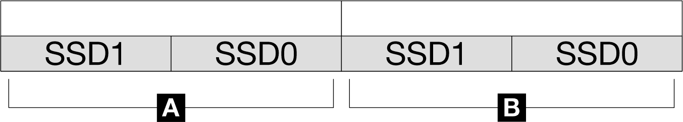
- Dual front drives configuration
E3.S 1T
Figure 2. E3.S 1T dual front drives configuration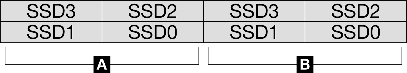
PCIe adapter configuration
Standalone PCIe configuration
Figure 3. Standalone PCIe configuration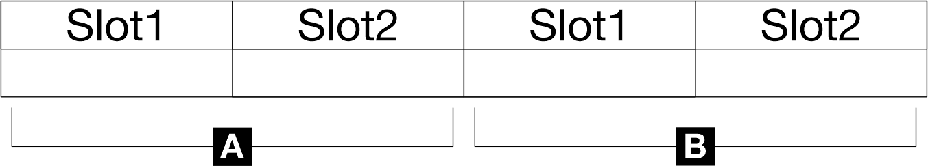
Socket direct PCIe configuration
Figure 4. Socket direct PCIe configuration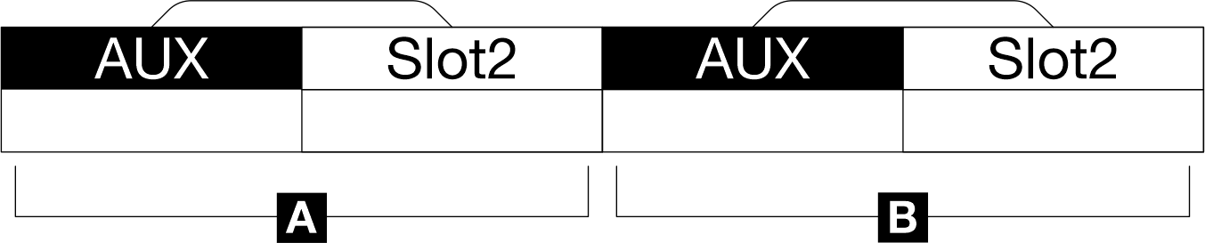
Shared I/O PCIe configuration
Figure 5. Shared I/O PCIe configuration—with single drive per cage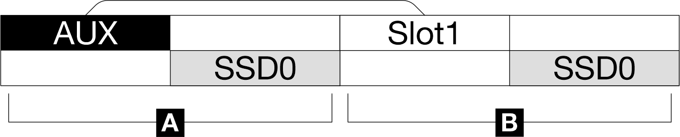 Figure 6. Shared I/O PCIe configuration—with dual drives per cage
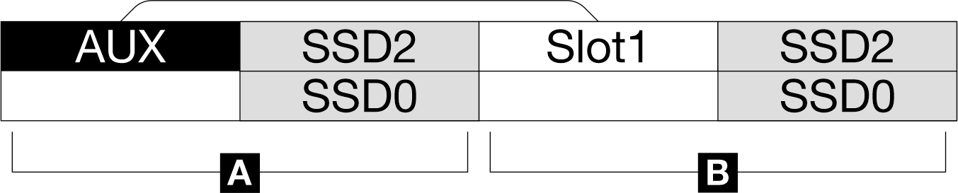
Give documentation feedback