Node top view
This section contains information on the top view of the node.
Node top view
Figure 1. Node top view
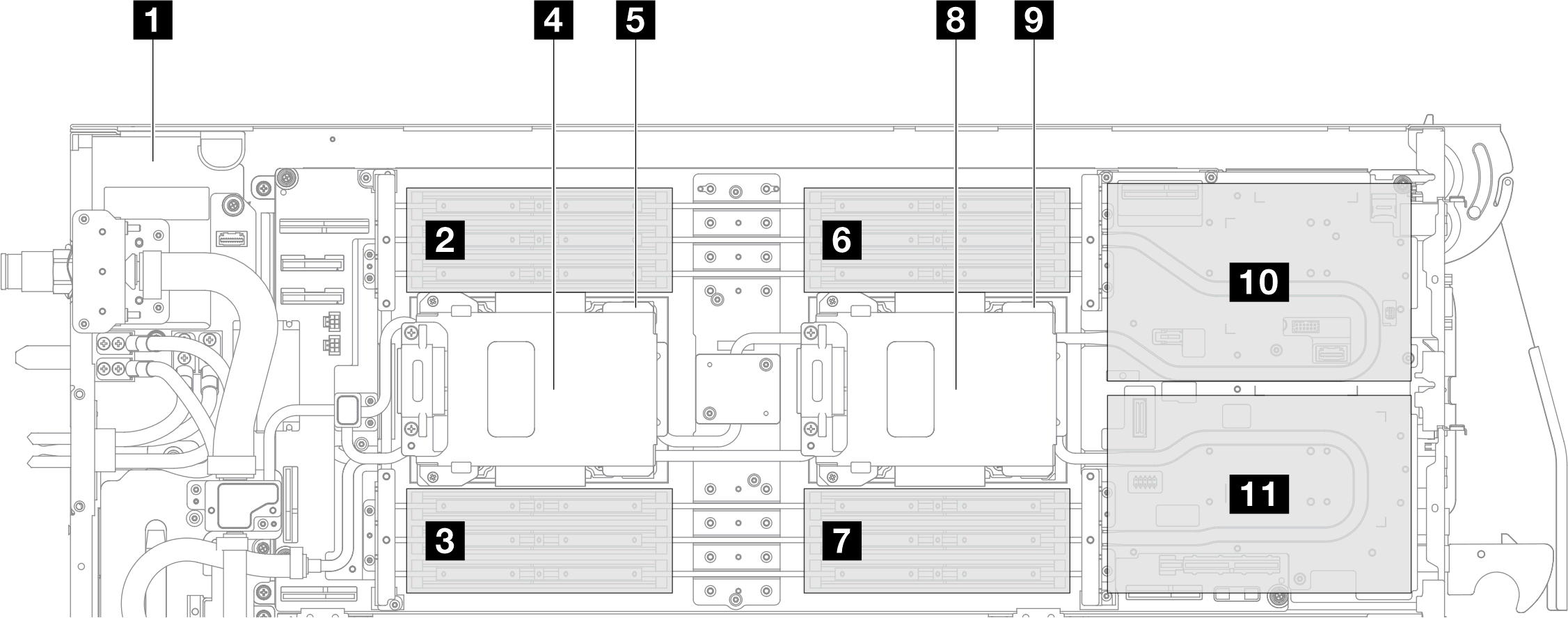
| 1 Power distribution board | 6 Memory module slot 1–6 |
| 2 Memory module slot 13–18 | 7 Memory module slot 7–12 |
| 3 Memory module slot 19–24 | 8 Drive 4 (E3.S 1T drive placed on top of processor 1 cold plate) |
| 4 Drive 5 (E3.S 1T drive placed on top of processor 2 cold plate) | 9 Processor 1 |
| 5 Processor 2 | 10 PCIe slot 2 / Drive 0, 2 11 PCIe slot 1 / Drive 1, 3 For information on PCIe adapter or drive configuration and numbering, see Front drive and PCIe adapter configuration. |
Give documentation feedback