Install a processor
This task has instructions for installing a processor. This task requires a Torx T30 driver.
About this task
Screwdriver for PH 1, PH 2, T10, and T30 screws
Waterloop Service Kit (SC750 V4) (The water loop carrier in the Service Kit is reusable, it is recommended to keep it at the facility where the server operates for future replacement needs.)
Up VR Gap Pad Kit (SC750 V4)
MID E3.S TOP Gap Pad (SC750 V4) , if E3.S middle drive is installed.
MID E3.S BOT Gap Pad (SC750 V4) , if E3.S middle drive is installed.
Storage Gap Pad Kit (SC750 V4) , if E3.S front drive is installed.
Storage Gap Pad Kit (SC750 V4) , if E3.S 1T dual front drives or E3.S 2T single front drive are installed.
CX7 NDR200 Gap Pad (SC750 V4) , if ConnectX-7 NDR 200 adapter is installed.
CX7 Gap Pad (SC750 V4) , if ConnectX-7 NDR 400 adapter is installed.
For gap pad location and instruction, see Gap pad identification and location.
Before replacing the gap pad, gently clean the surface with an alcohol cleaning pad.
Hold the gap pad carefully to avoid deformation. Make sure no screw hole or opening is blocked by the gap pad material.


Read Installation Guidelines and Safety inspection checklist to ensure that you work safely.
Turn off the corresponding DWC tray that you are going to perform the task on.
Disconnect all external cables from the enclosure.
Use extra force to disconnect QSFP cables if they are connected to the solution.
Each processor socket must always contain a cover. When removing or installing a processor, protect empty processor sockets with a cover.
Do not touch the processor socket or processor contacts. Processor-socket contacts are very fragile and easily damaged. Contaminants on the processor contacts, such as oil from your skin, can cause connection failures.
Do not allow the thermal grease on the processor or water loop to come in contact with anything. Contact with any surface can compromise the thermal grease, rendering it ineffective. Thermal grease can damage components, such as electrical connectors in the processor socket. Do not remove the grease cover from the cold plate until you are instructed to do so.
Before you install a new or replace a processor, update your system firmware to the latest level. See Update the firmware.
To avoid damaging the water loop, always use the water loop carrier when removing, installing or folding the water loop.
See Lenovo ServerProven website for a list of processors supported for your system. All processors on the system board must have the same speed, number of cores, and frequency.
Optional devices available for your system might have specific processor requirements. See the documentation that comes with the optional device for information.
Go to Drivers and Software download website for ThinkSystem SC750 V4 to see the latest firmware and driver updates for your server.
Go to Update the firmware for more information on firmware updating tools.
- A video of this procedure is available at YouTube.
Procedure
- Clean the thermal grease on water loop processor cold plate.
- Apply the thermal grease on the top of the processor with syringe by forming four uniformly spaced dots, while each dot consists of about 0.1 ml of thermal greaseNoteCarefully place the processor and retainer on a flat surface with the processor-contact side down.Figure 2. Thermal grease application
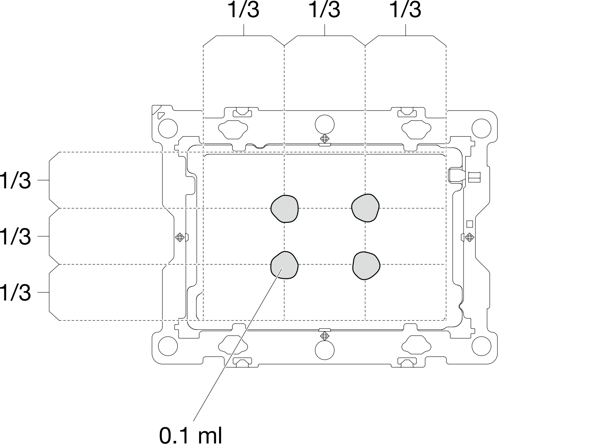
- Apply the thermal grease on the top of the processor with syringe by forming four uniformly spaced dots, while each dot consists of about 0.1 ml of thermal grease
- Install processor retainers onto processor if needed.
- Gently place the processor retainer on the processor; then, carefully press the four sides of the processor retainer to secure the processor.Figure 3. Installing a processor retainer
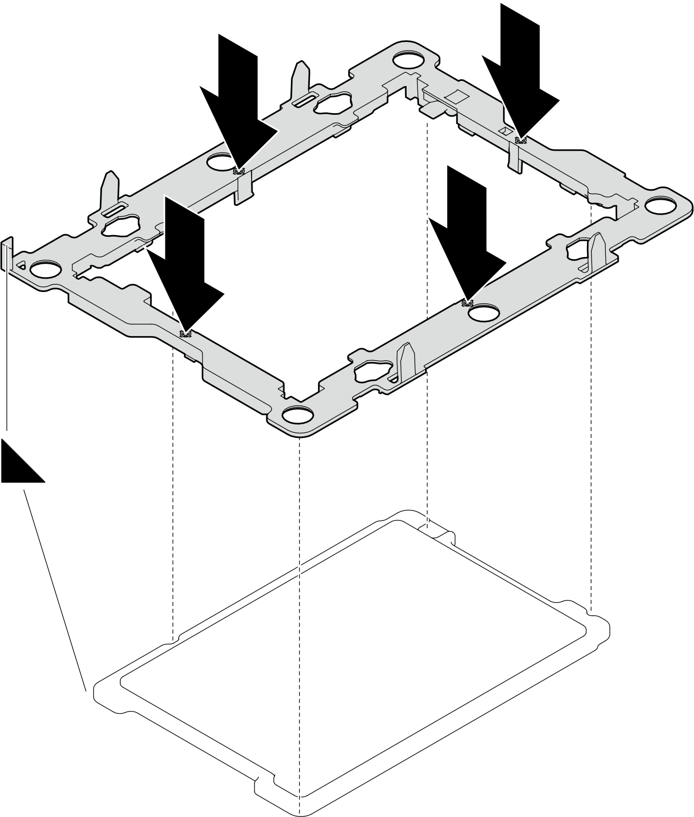
- Gently place the processor retainer on the processor; then, carefully press the four sides of the processor retainer to secure the processor.
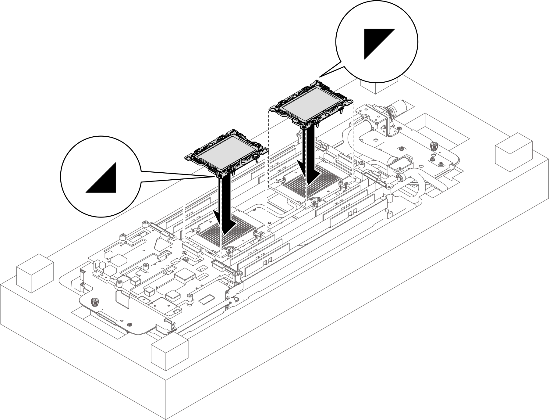
- Install the processor to the water loop. Align the triangular marks on the processor retainers with the triangular slots on the underside of the water loop cold plate; then, attach the processors to the underside of the water loop cold plate by inserting the processor retainer posts and clips features into the openings at the four corners of the cold plate.Figure 4. Installing processor to the water loop
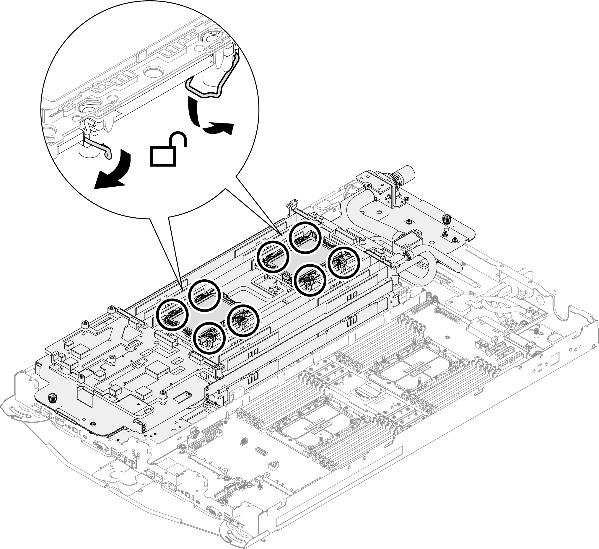
- Rotate all anti-tilt wire bails (8x anti-tilt wire bails per node) outwards to the unlocked position.Figure 5. Unlocking Torx T30 captive screws
- Check the gap pads on the water loop, if any of them are damaged or detached, replace them with new ones.Figure 6. Water loop gap pads locations
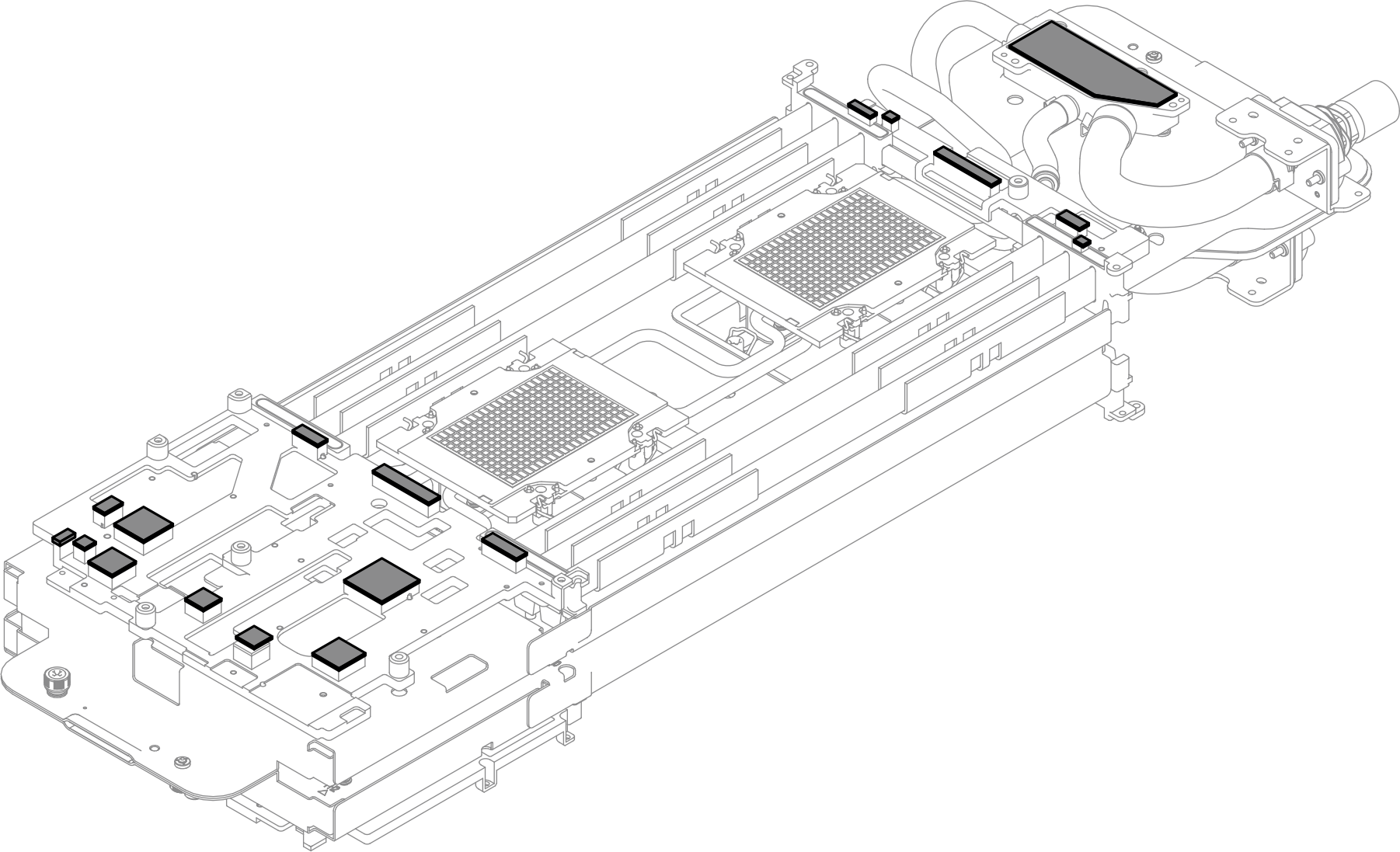
Make sure to follow Gap pad replacement guidelines.
- Check the gap pads on the VR cold plate installed on the processor board, if any of them are damaged or detached, replace them with new ones.Figure 7. VR cold plate gap pads locations
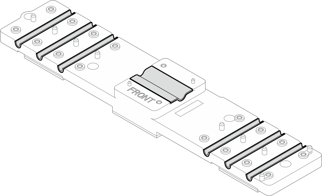
Make sure to follow Gap pad replacement guidelines.
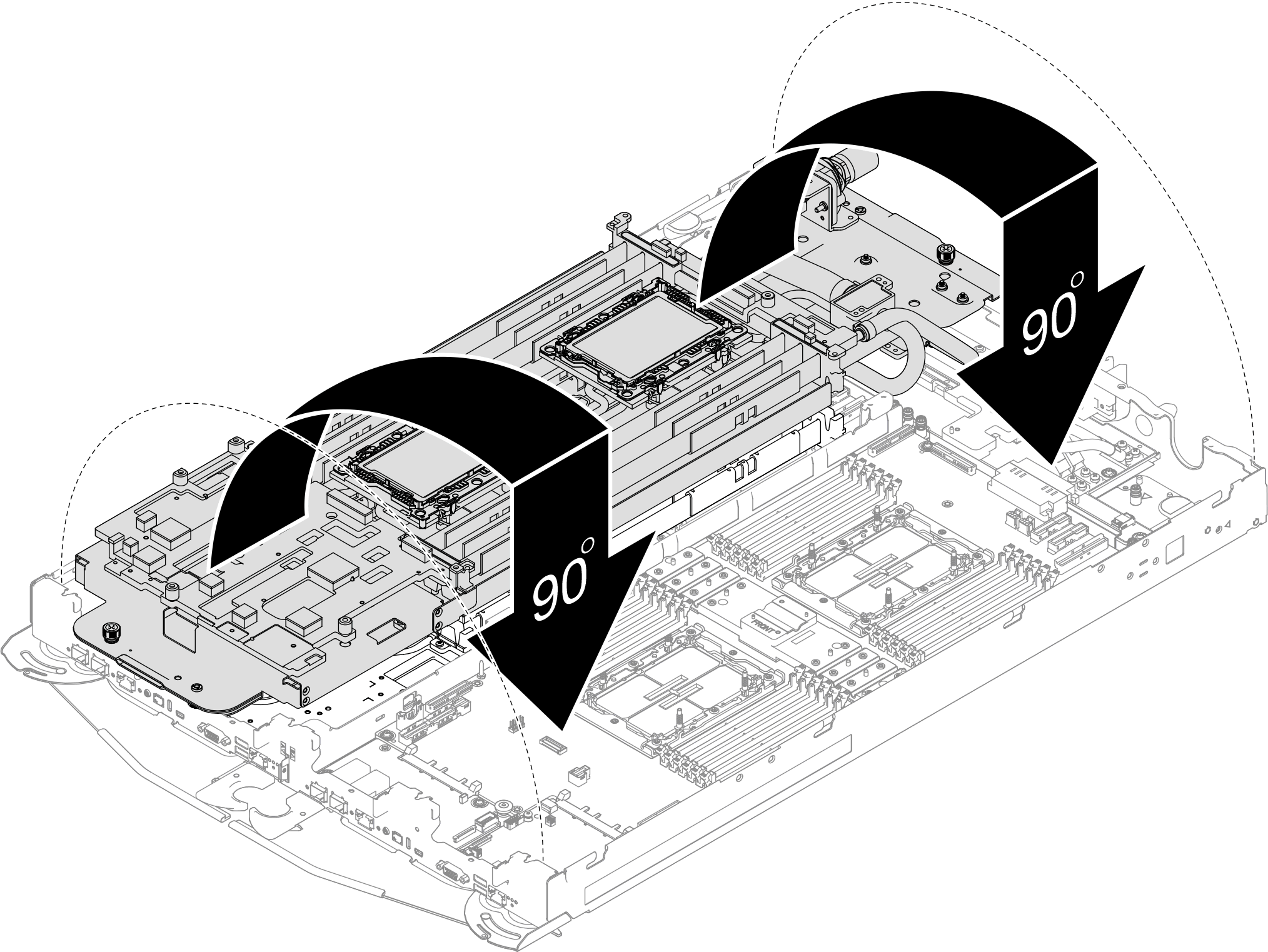
- Carefully rotate the top side of the water loop, position the water loop on the two guide pins near the rear of the node; then, gently put the water loop down and ensure it is firmly seated on the system board.Figure 8. Water loop installation
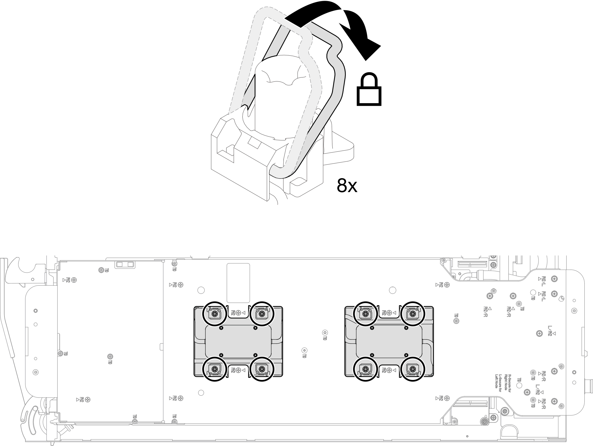
- Rotate anti-tilt wire bails (8x anti-tilt wire bails per node) outwards to the locked position.Figure 9. Unlocking anti-tilt wire bails
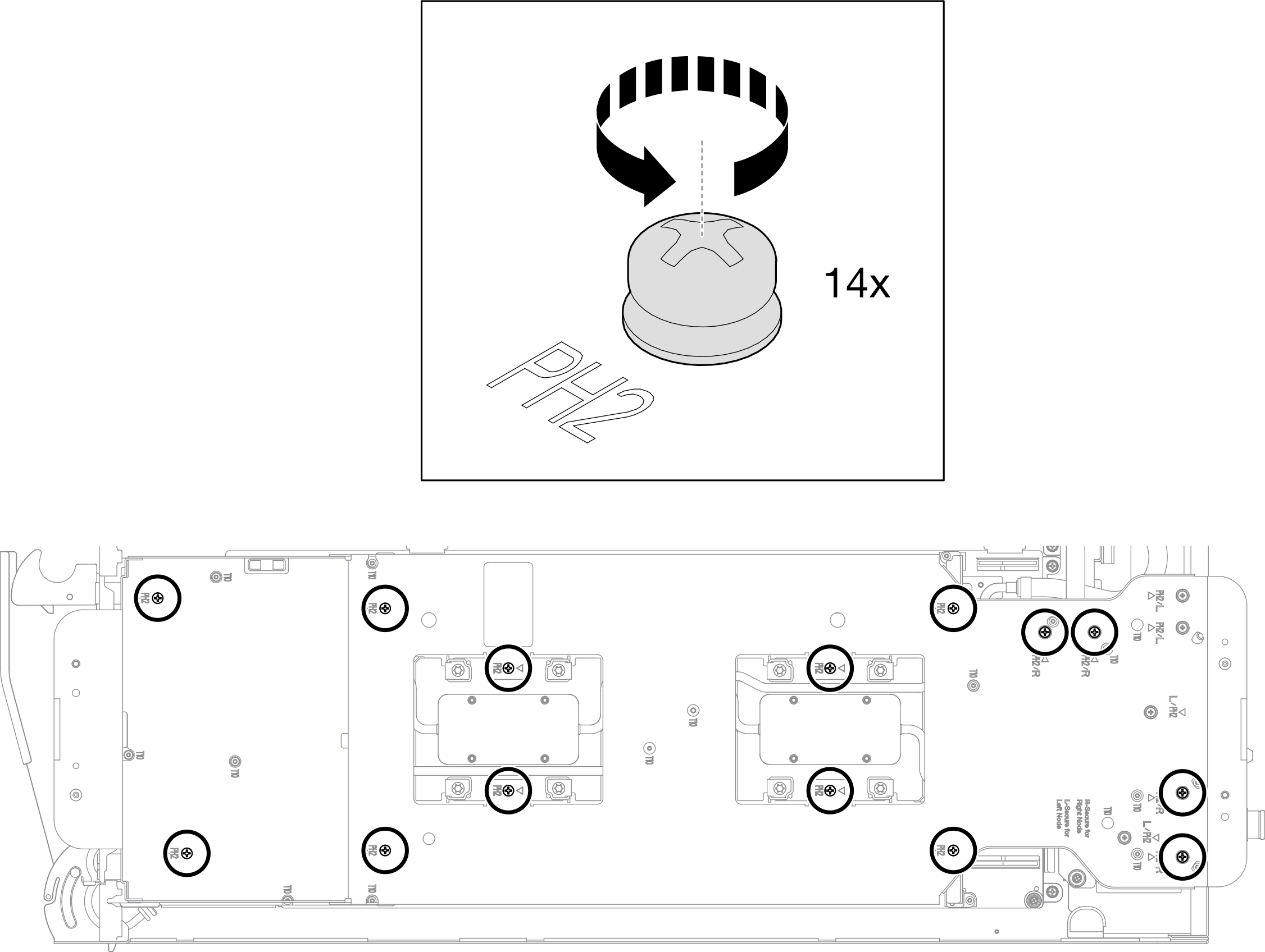
- Loosen water loop carrier screws (14x Phillips #2 screws for two nodes).Figure 10. Loosening water loop carrier screws
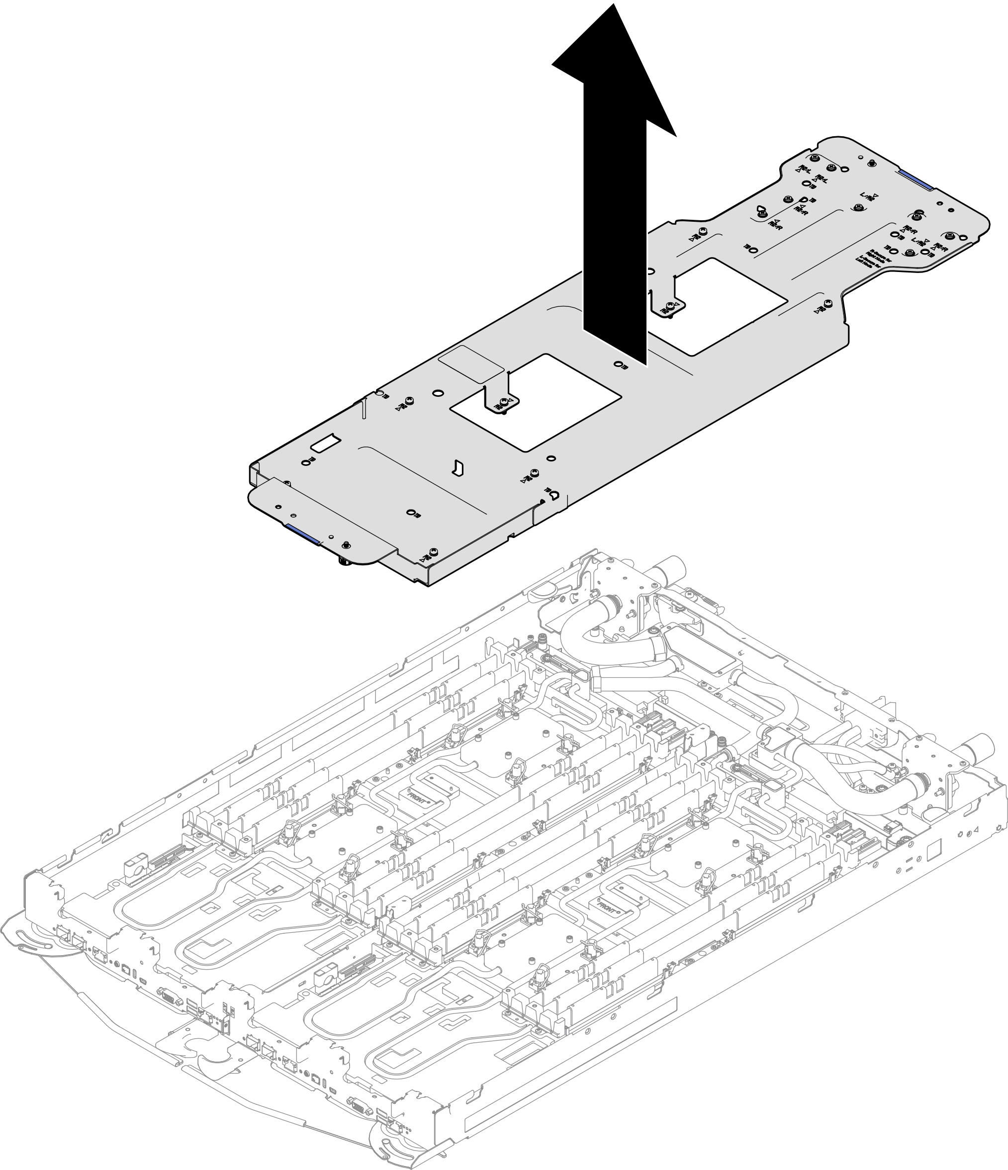
- Carefully lift the water loop carrier up and away from the water loop.Figure 11. Water loop carrier removal
- Fully tighten all Torx T30 captive screws (8x Torx T30 captive screws for two nodes) following the screw sequence label on the shipping bracket, with a torque screwdriver set to the proper torque.Note
For reference, the torque required for the screws to be fully tightened/removed is 8+/- 0.5 lbf-in, 0.9+/- 0.05 N-m.
To prevent damage to components, make sure that you follow the indicated tightening/loosening sequence.
Figure 12. Screw tightening/loosening sequence on the shipping bracket label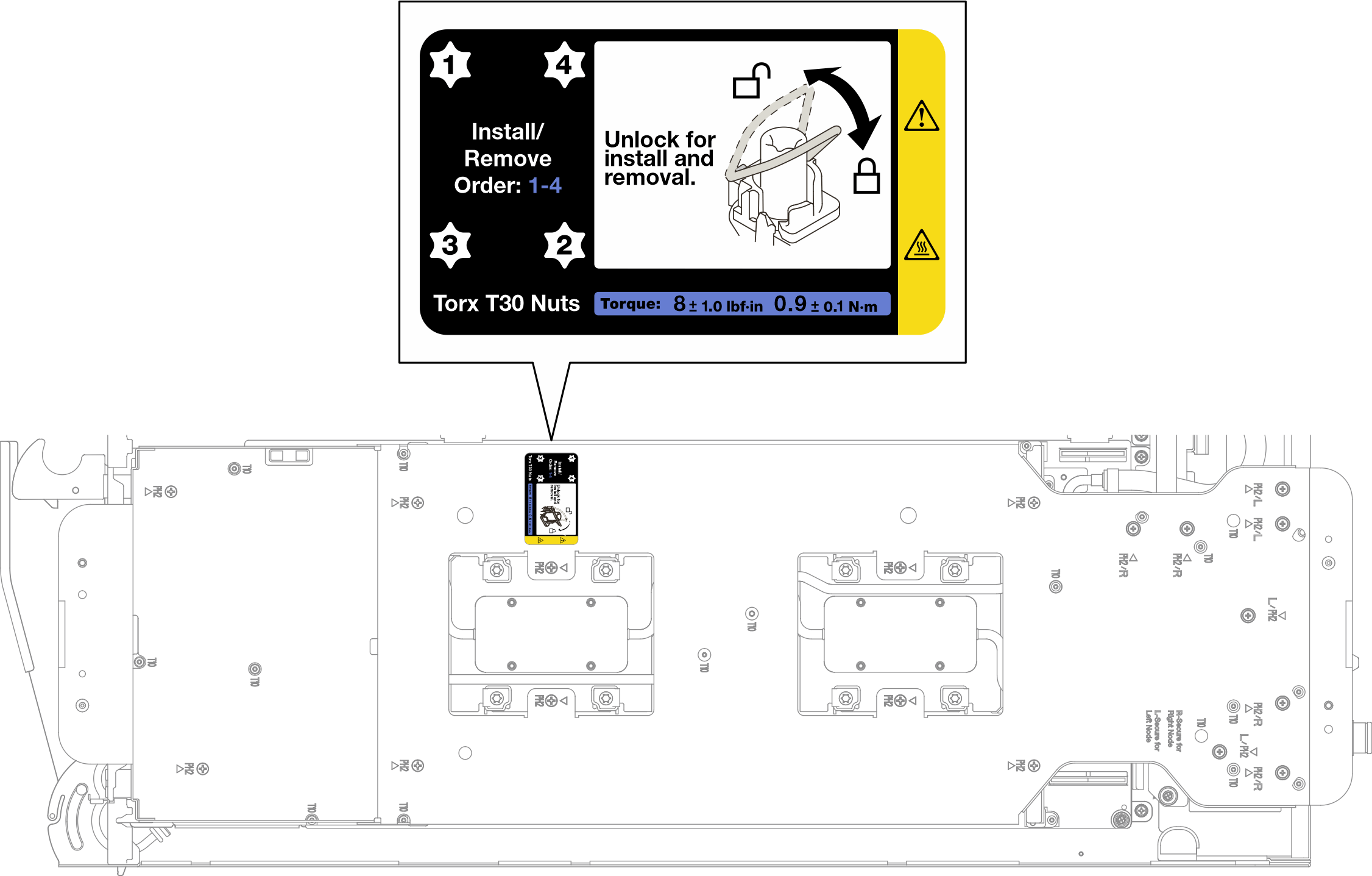 Figure 13. Tightening Torx T30 captive screws
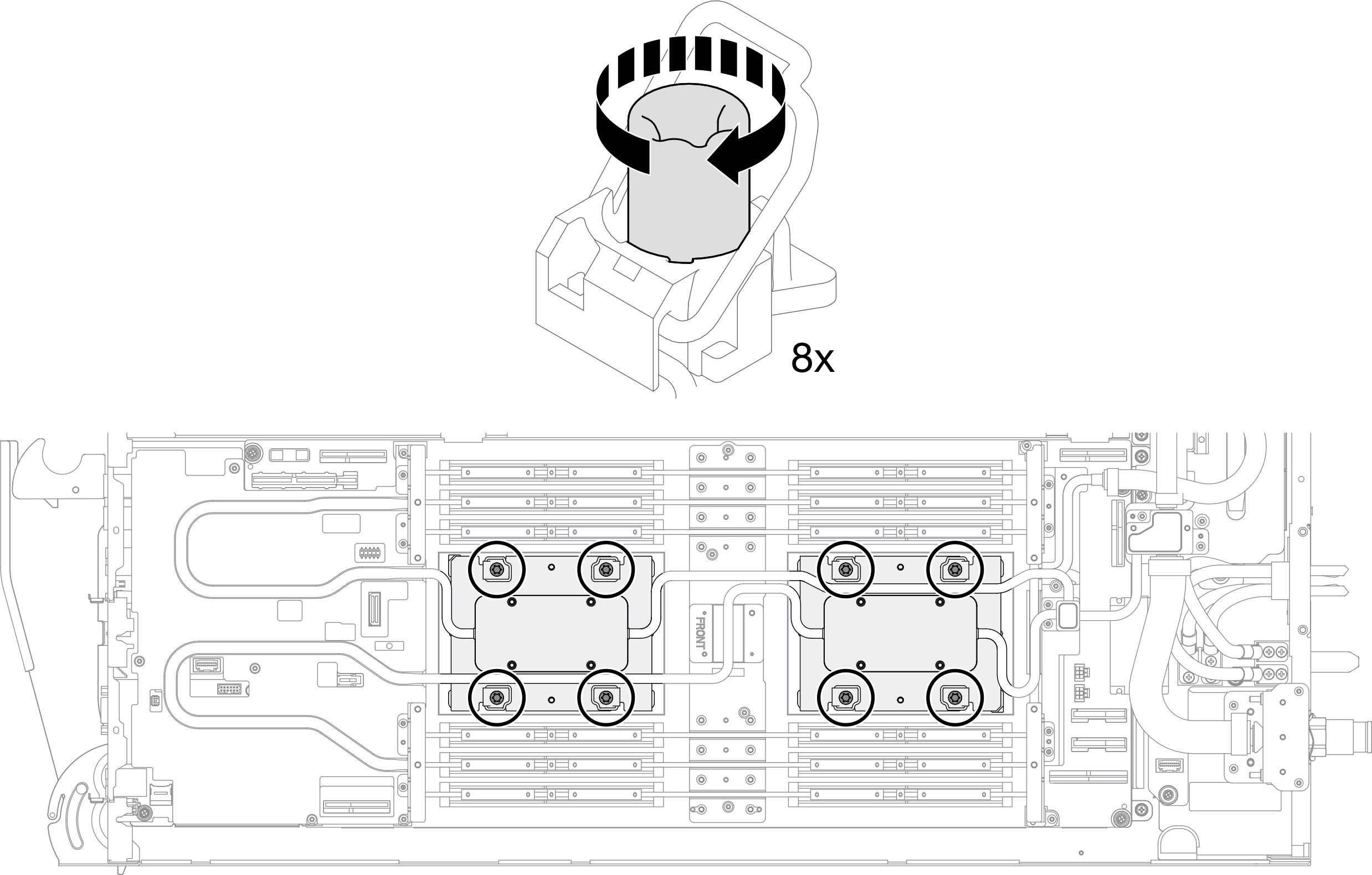
- Install water loop screws (9x Torx T10 screws per node) with a torque screwdriver set to the proper torque.Note
For reference, the torque required for the screws to be fully tightened/removed is 5.0+/- 0.5 lbf-in, 0.55+/- 0.05 N-M.
Figure 14. Water loop screws installation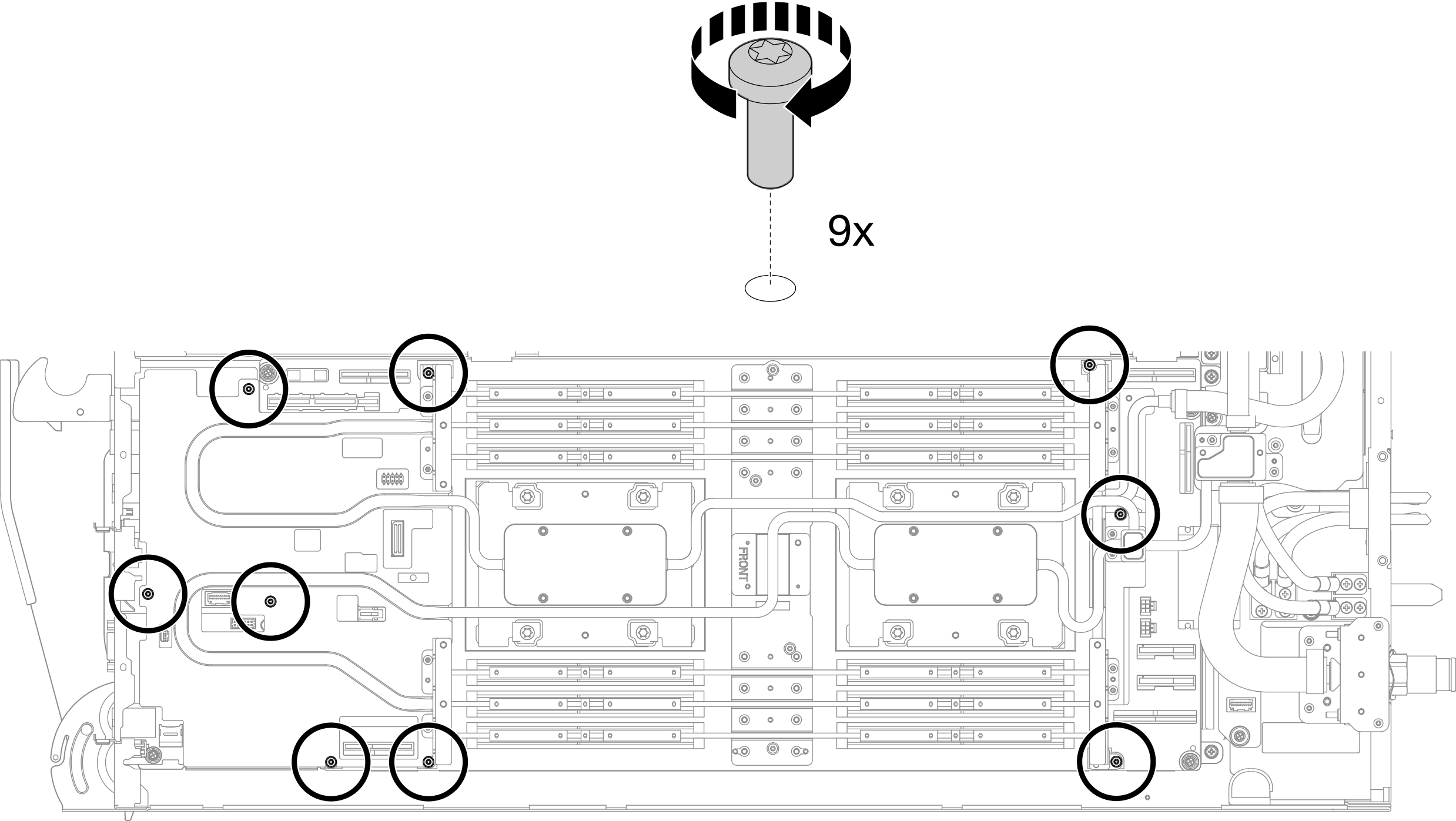
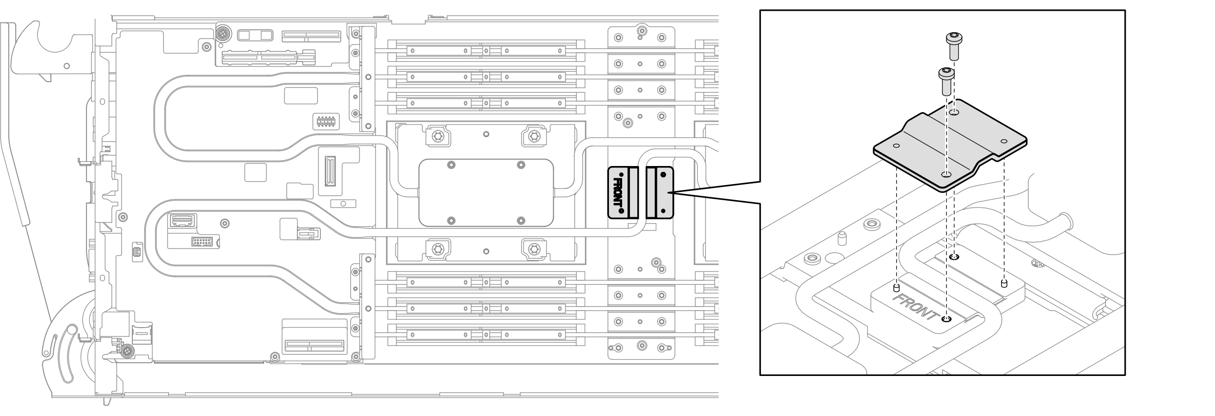
- Install three Torx T10 screws to secure mixing chambers to the power distribution board cold plate with a torque screwdriver set to the proper torque.Note
For reference, the torque required for the screws to be fully tightened/removed is 5.0+/- 0.5 lbf-in, 0.55+/- 0.05 N-M.
Figure 15. Mixing chamber screws installation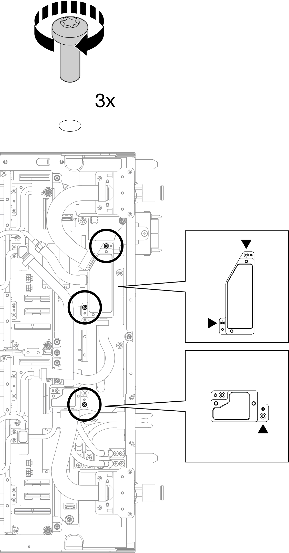
- Install four (4x) Torx T10 screws to secure the two quick connects to the tray.
 Install the Torx T10 screws to secure the quick connect to the tray.
 Install the Torx T10 screws to secure the quick connect to the power distribution board.
NoteFor reference, the torque required for the screws to be fully tightened/removed is 5.0+/- 0.5 lbf-in, 0.55+/- 0.05 N-M.
Figure 16. Quick connect screw installation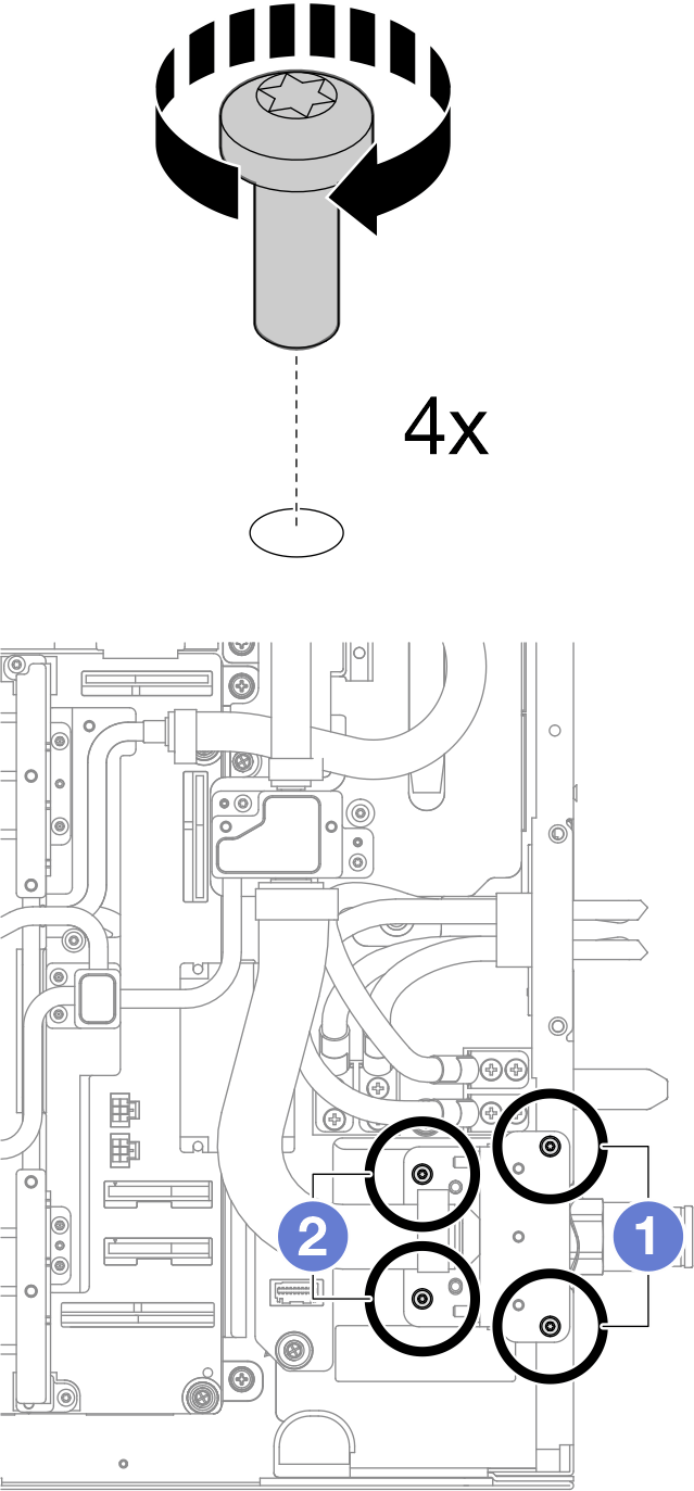
- Install the VR cover to the water loop.Figure 17. Installing the VR cover
- Check the gap pad on the top side of the E3.S middle cold plate, if it is damaged or detached, replace them with new one.Figure 18. E3.S middle cold plate top side gap pad location
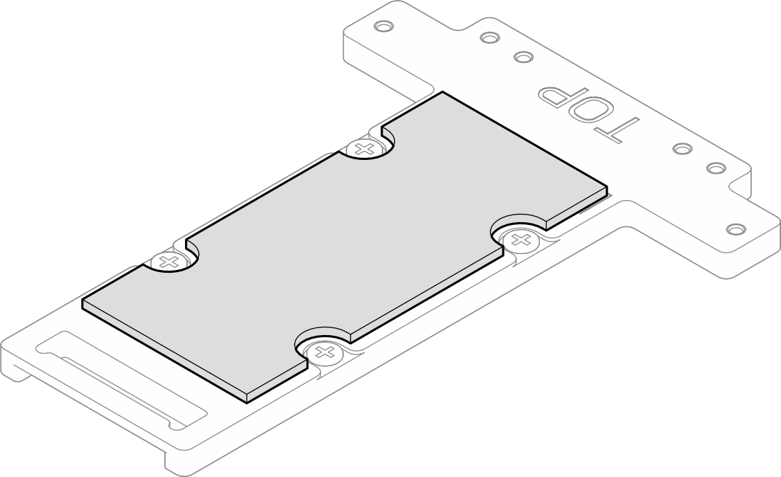
Make sure to follow Gap pad replacement guidelines.
- Replace the single-use gap pad on bottom side of the E3.S middle cold plate a with new one.Figure 19. E3.S middle cold plate bottom side single-use gap pad location
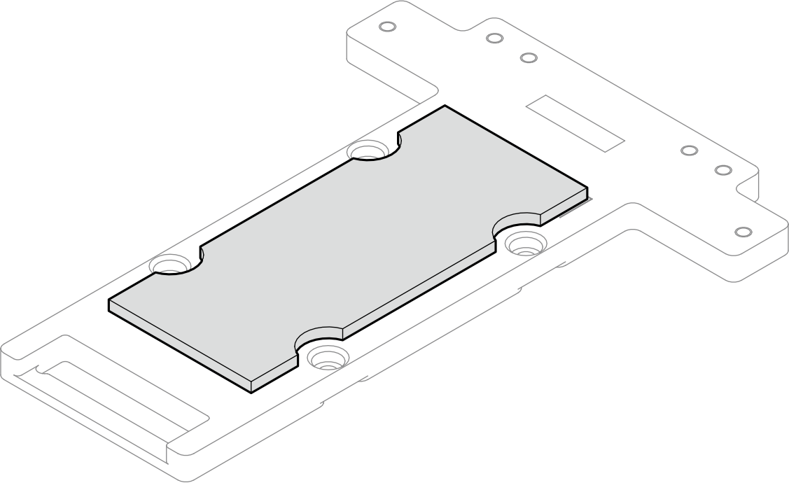
Make sure to follow Gap pad replacement guidelines.
- Install four PH1 screws to install the middle drive cold plates to the water loop. Make sure to keep the
TOP
marking facing the rear of tray.NoteFor reference, the torque required for the screws to be fully tightened/removed is 5.0+/- 0.5 lbf-in, 0.55+/- 0.05 N-M.
Make sure to install all four middle drive cold plates to the water loop (two cold plates per node).
Figure 20. Install the middle drive cold plate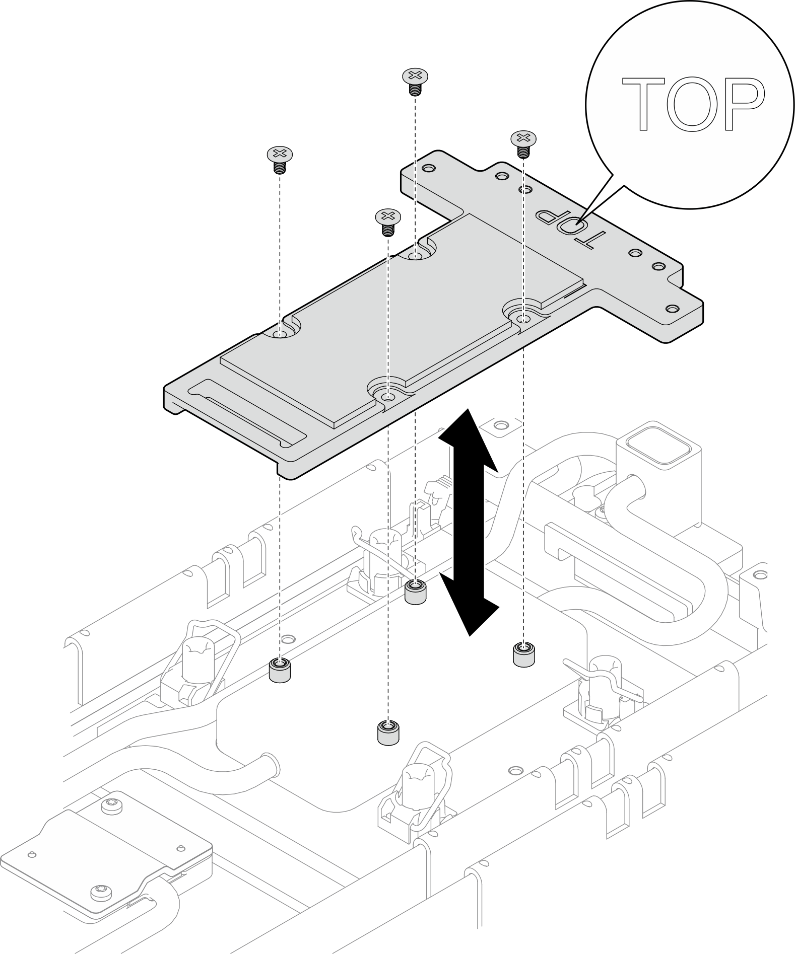
Install the leakage sensor. See Install the leakage sensor.
Install the sideband cable kit. See Install the system management sideband cable kit.
Install the middle E3.S drive cage. See Install an E3.S 1T middle drive cage assembly.
- Install the PCIe adapter riser cage. See Install a ConnectX-7 NDR 200 adapter riser assembly or Install a ConnectX-7 NDR 400 adapter riser assembly.
Install the front E3.S drive cage. See Install an E3.S front drive cage assembly.
If the system will be installed with memory modules that requires dual-side cooling, install DIMM cooling bars. See Install a DIMM cooling bar.
Install the cross braces. See Install the cross braces.
Install the memory module, perform one of the following.
Install the memory modules that require single-side cooling. See Install a memory module (single-side cooling)., or
Install the memory modules that require dual-side cooling. See Install a memory module (dual-side cooling).
Install the DIMM comb. See Install a DIMM comb.
Install the tray cover. See Install the tray cover.
Install the tray into the enclosure. See Install a tray in the enclosure.
- Connect all required external cables to the solution.NoteUse extra force to connect QSFP cables to the solution.
- Check the power LED on each node to make sure it changes from fast blink to slow blink to indicate all nodes are ready to be powered on.Note
Shared I/O configuration requires specific nodes power-on sequence. When powering on the system, power on Node B first; then, power on Node A. For more information, see PCIe adapter cable routing.