Instradamento dei cavi del modulo del sensore di rilevamento delle perdite
Utilizzare questa sezione per comprendere l'instradamento dei cavi del modulo del sensore di rilevamento delle perdite.
Nota
Connessioni tra i connettori; 1↔1, 2↔2, 3↔3, ... n↔n
Quando si instradano i cavi, verificare che tutti i cavi siano instradati correttamente attraverso le guide dei cavi e i fermacavi corrispondenti.
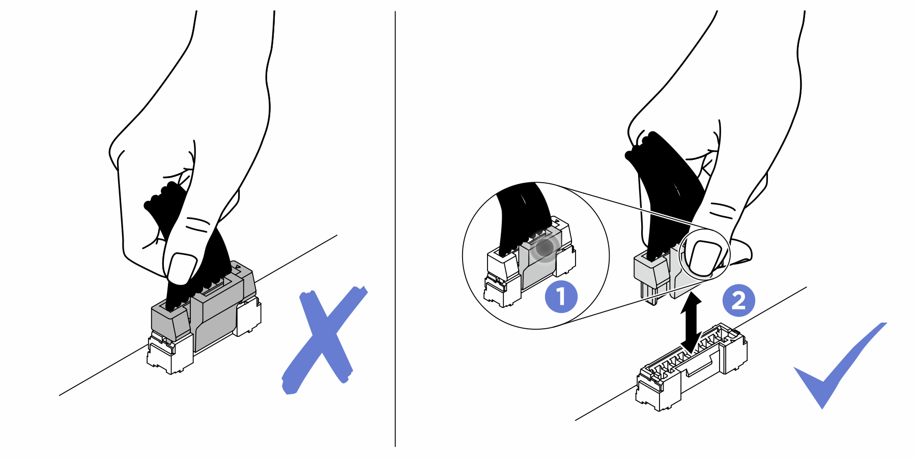
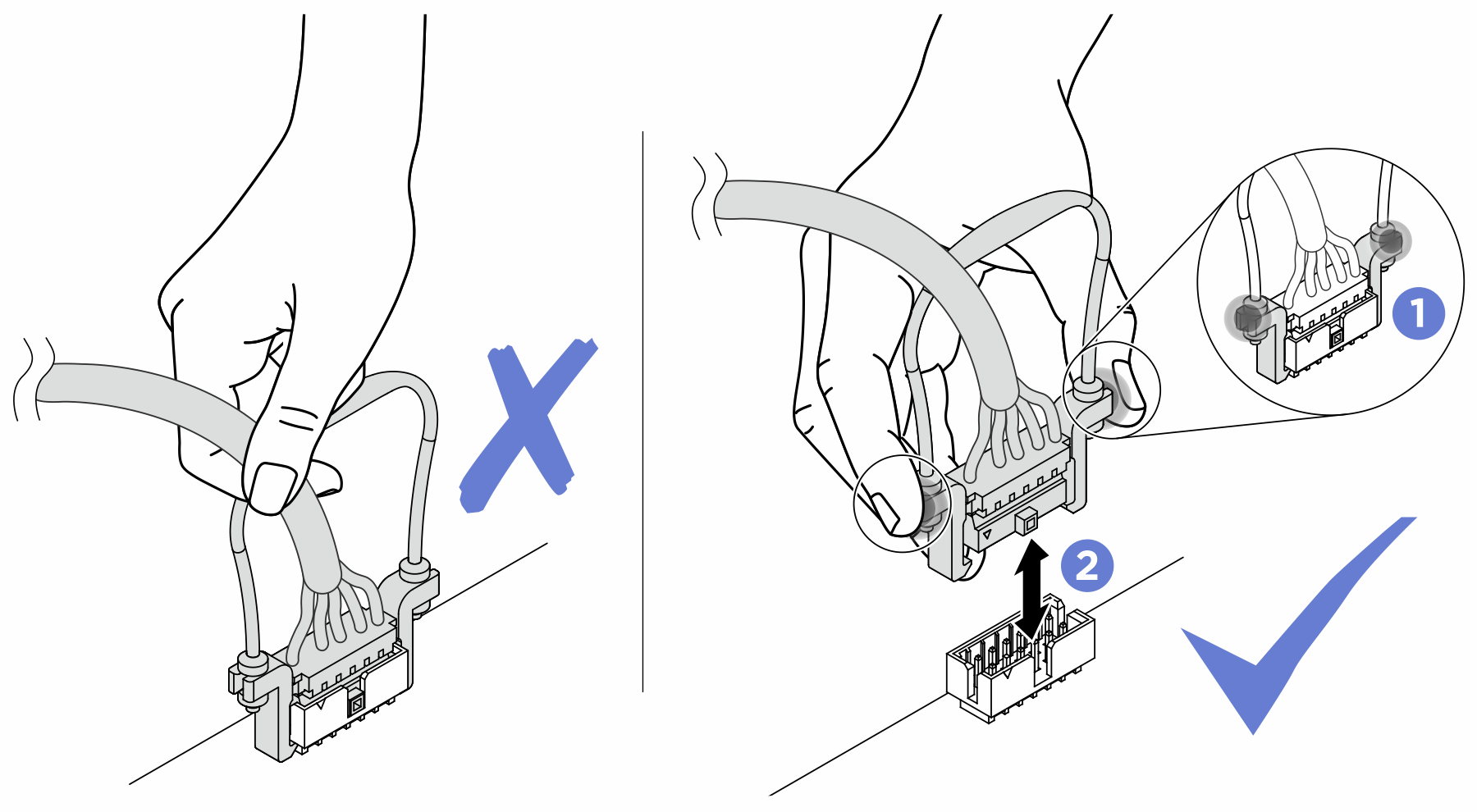
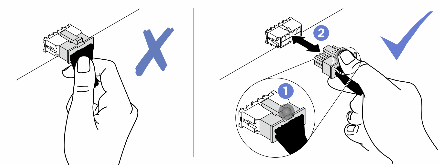
- Attenersi scrupolosamente alle istruzioni riportate di seguito per evitare di danneggiare i socket dei cavi sulla scheda di sistema. Un qualsiasi danno ai socket dei cavi potrebbe richiedere la sostituzione della scheda di sistema.
Collegare i connettori dei cavi verticalmente oppure orizzontalmente allineandoli agli orientamenti dei socket dei cavi corrispondenti, evitando qualsiasi inclinazione.
- Per scollegare i cavi dalla scheda di sistema, procedere nel modo seguente:
Tenere premuti tutti i fermi, le linguette di rilascio o i blocchi sui connettori dei cavi per rilasciare i connettori dei cavi.
- Rimuovere i connettori dei cavi verticalmente o orizzontalmente allineandoli agli orientamenti dei socket dei cavi corrispondenti, evitando qualsiasi inclinazione.NotaI connettori dei cavi potrebbero avere un aspetto diverso da quelli presenti nell'illustrazione, ma la procedura di rimozione è identica.
Instradamento dei cavi del modulo del sensore di rilevamento delle perdite
Nota
Per una migliore disposizione del cavo, è necessario installare i tubi e il modulo del sensore di rilevamento delle perdite in un supporto designato e assicurarsi che il modulo sia fissato nei fermi del supporto. Per maggiori dettagli, vedere la seguente figura o Installazione del Lenovo Processor Neptune® Core Module.
Figura 1. Instradamento dei cavi del modulo del sensore di rilevamento delle perdite
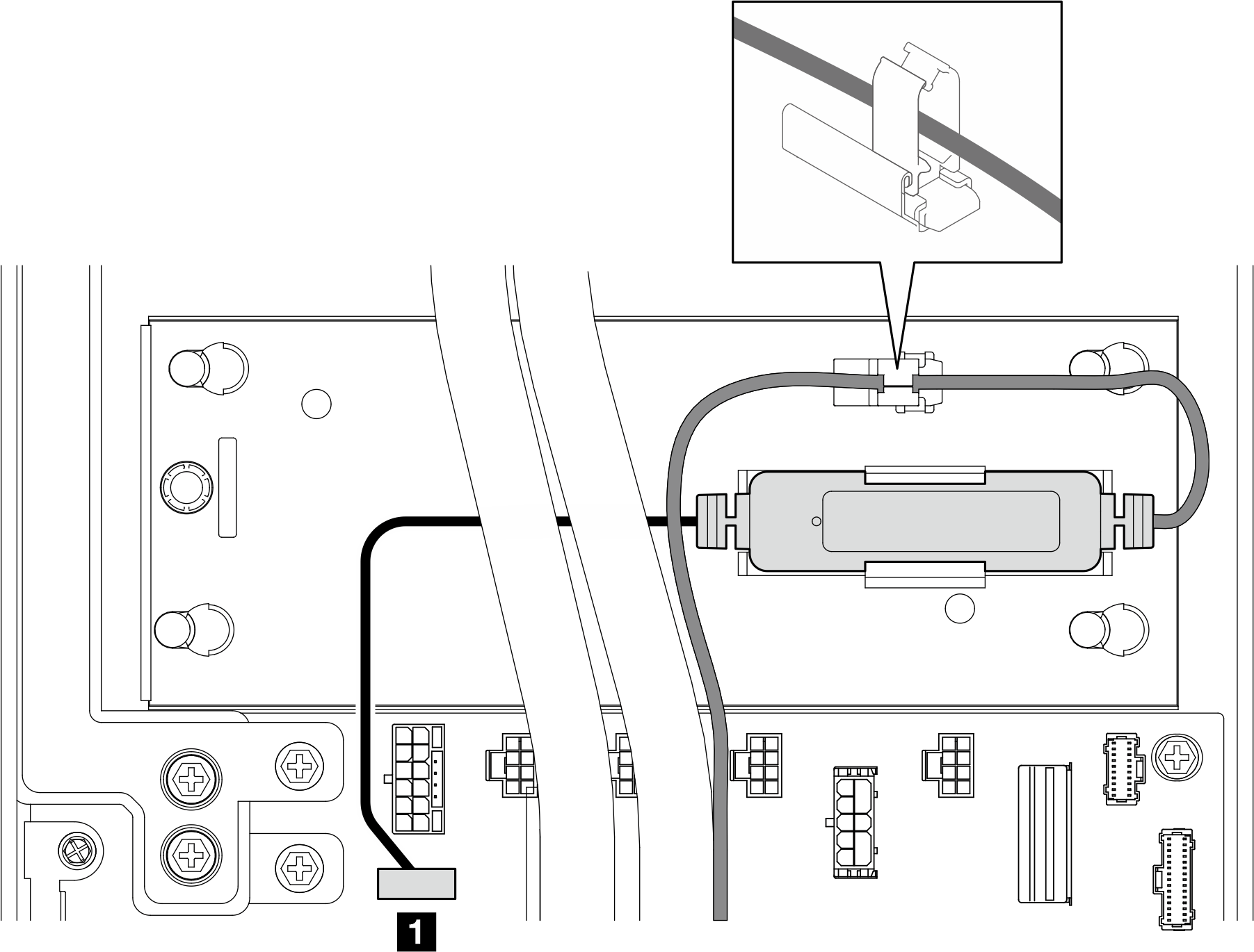
| Cavo | Da | A |
|---|---|---|
| 1 Cavo del modulo del sensore di rilevamento delle perdite | Modulo del sensore di rilevamento delle perdite | Scheda di sistema: connettore del modulo del sensore di rilevamento delle perdite (LIQUID) |
Envoyer des commentaires