PCIe riser cable routing
Follow instructions in this section to route the cables for the PCIe riser.
Note
- Depending on the specific configuration, the information in this topic might not apply to your node.
Connections between connectors; 1↔1, 2↔2, 3↔3, ... n↔n
When routing the cables, make sure that all cables are routed appropriately through the corresponding cable guides and cable clips.
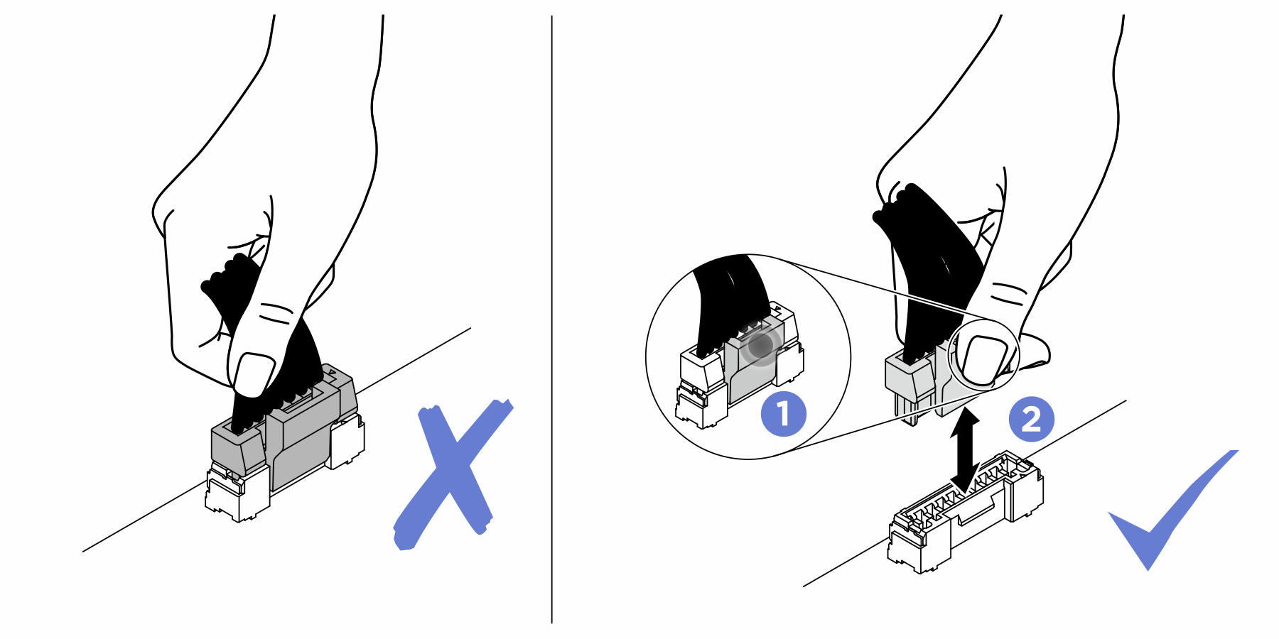
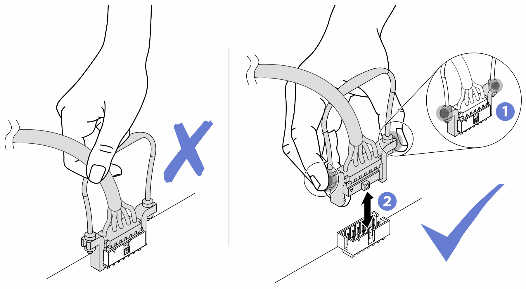
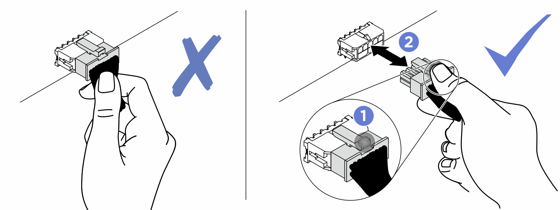
- Strictly observe the following instructions to avoid damaging cable sockets on the system board. Any damage to the cable sockets might require replacing the system board.
Connect cable connectors vertically or horizontally in alignment with the orientations of the corresponding cable sockets, avoiding any tilt.
- To disconnect cables from the system board, do as follows:
Press and hold all latches, release tabs, or locks on cable connectors to release the cable connectors.
- Remove the cable connectors vertically or horizontally in alignment with the orientations of the corresponding cable sockets, avoiding any tilt.NoteThe cable connectors might look different from those in the illustration, but the removal procedure is the same.
The PCIe riser cable routing contains the following configurations:
With one processor
Figure 1. PCIe riser cable routing – one processor
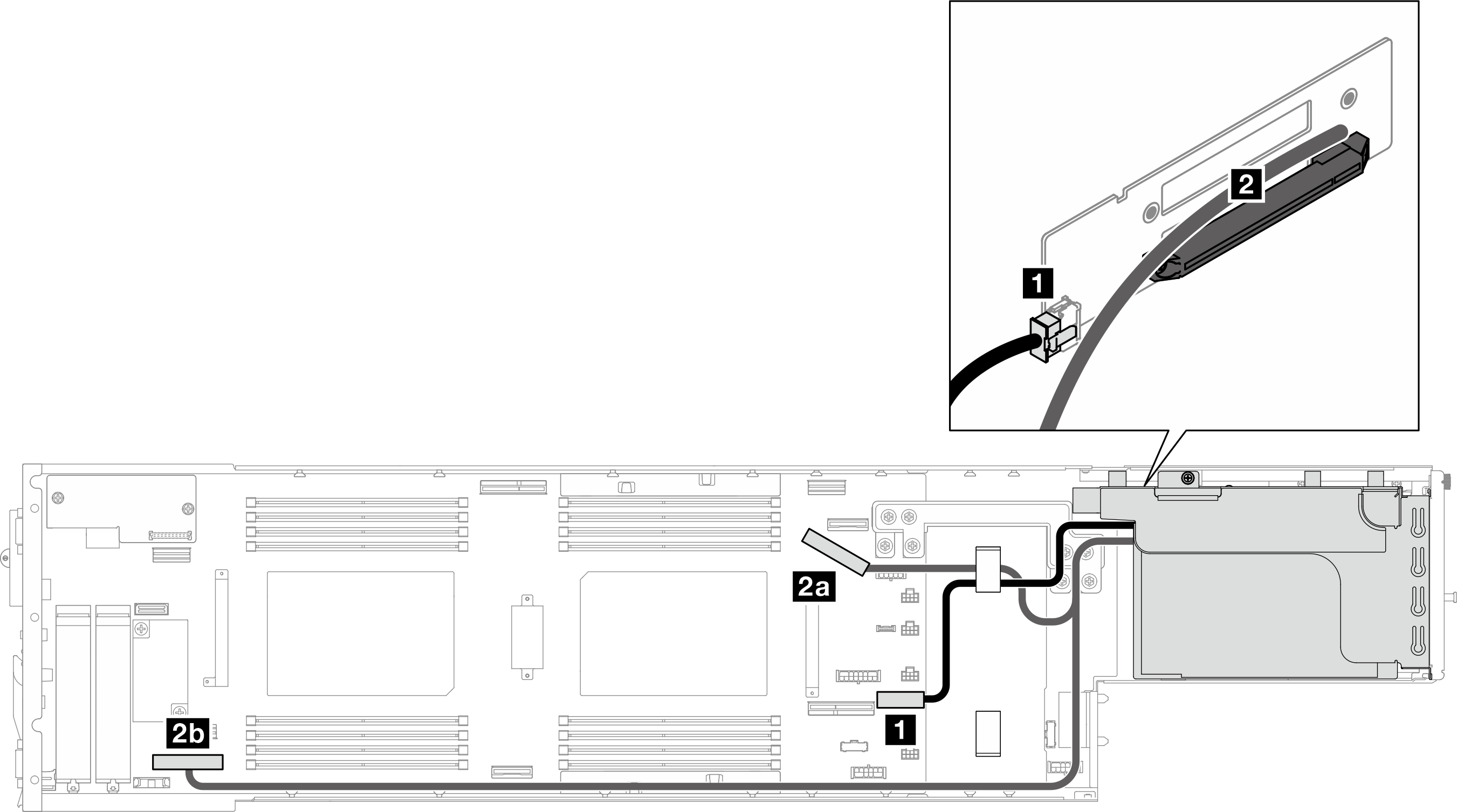
| From (system board) | To (PCIe riser) | Cable |
|---|---|---|
| 1 PCIe riser power connector | 1 Power connector | Power 2x8 to power 2x4 (290 mm) |
| 2a PCIe riser (1S) sideband connector | 2 PCIe riser wired cable (Slot 2) | MCIO x16 (270 mm) |
| 2b PCIe riser (1S) connector | MCIO x16 (780 mm) |
With two processors
Figure 2. PCIe riser cable routing – two processors
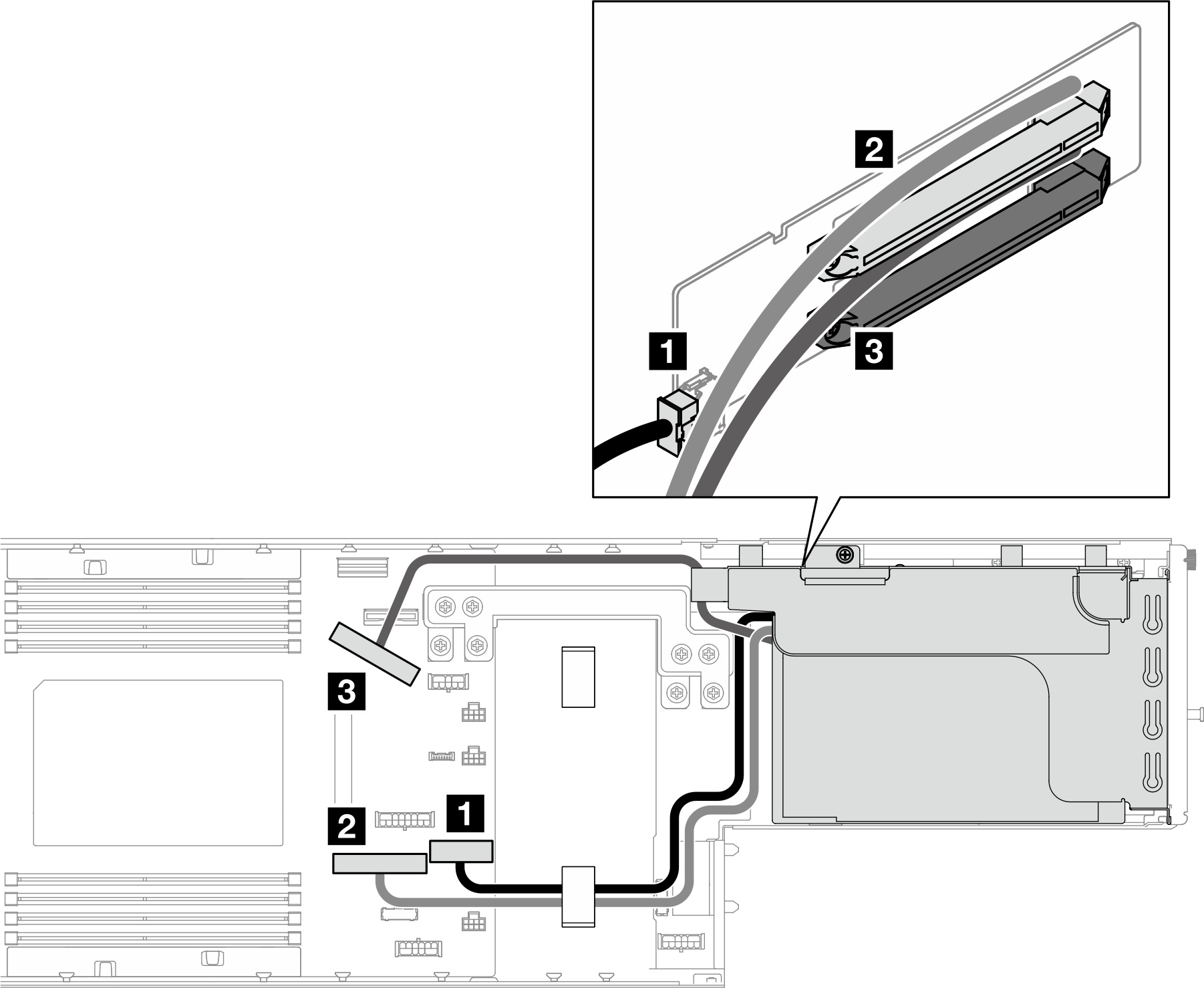
| From (system board) | To (PCIe riser) | Cable |
|---|---|---|
| 1 PCIe riser power connector | 1 Power connector | Power 2x8 to power 2x4 (290 mm) |
| 2 PCIe riser slot 1 connector (Gen4) | 2 PCIe riser wired cable (Slot 1) | MCIO x16 (360 mm) |
| 3 PCIe riser slot 2 connector (Gen5) | 3 PCIe riser wired cable (Slot 2) | MCIO x16 (260 mm) |
Give documentation feedback