Install a hot-swap power supply
Follow instructions in this section to install a power supply unit (PSU).
About this task
To avoid potential danger, make sure to read and follow the safety information.

To avoid a shock hazard:
- Connect all power cords to a properly wired and grounded electrical outlet/source.
- Connect any equipment that will be attached to this product to properly wired outlets/sources.
- When possible, use one hand only to connect or disconnect signal cables.
- Never turn on any equipment when there is evidence of fire, water, or structural damage.
- The device might have more than one power cord, to remove all electrical current from the device, ensure that all power cords are disconnected from the power source.
Never remove the cover on a power supply or any part that has this label attached. Hazardous voltage, current, and energy levels are present inside any component that has this label attached. There are no serviceable parts inside these components. If you suspect a problem with one of these parts, contact a service technician.

High touch current. Connect to earth before connecting to supply.
Read Installation Guidelines and Safety inspection checklist to make sure that you work safely.
- The following notes describe the type of power supply that the chassis supports and other information that you must consider when installing a power supply:
- For redundancy support, an additional hot-swap power supply must be installed, if one is not installed in the chassis.
- Make sure that the devices that you are installing are supported. For a list of supported optional devices for the chassis, see Lenovo ServerProven website.
Procedure
- Make preparations for this task.
- If a PSU filler is installed in the PSU slot, remove it.
 Press and hold the tab on the PSU filler.
 Pull the filler out of the PSU slot.Figure 1. Removal of a PSU filler
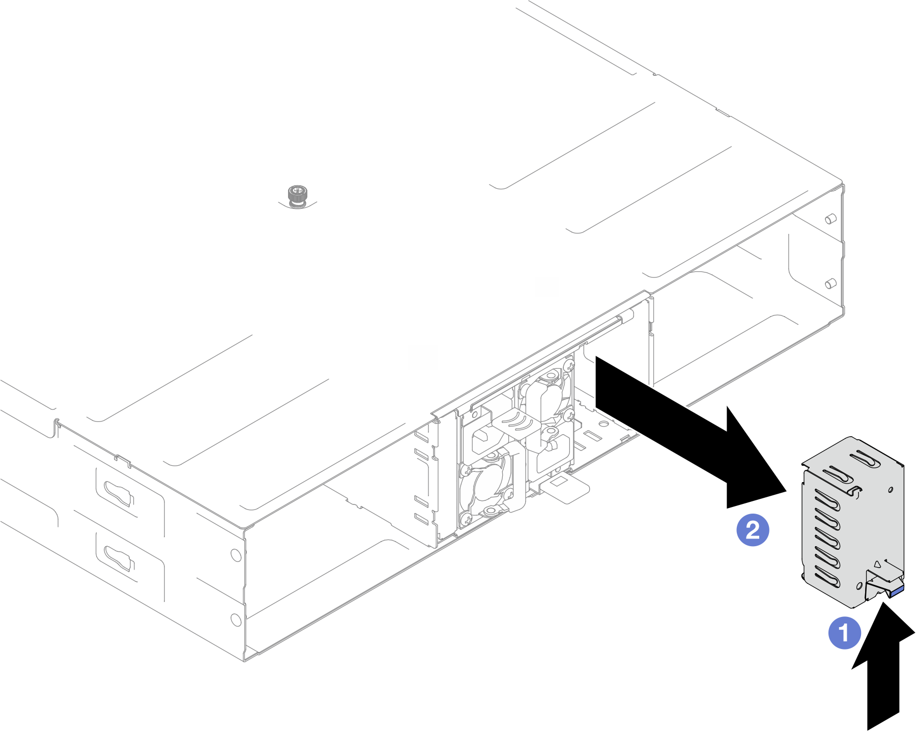
- If a PSU filler is installed in the PSU slot, remove it.
- Insert the hot-swap power supply into the slot until the release tab clicks into place.Important
- During normal operation, each power-supply slot must contain either a power supply or power-supply filler for proper cooling.
- Make sure to follow the instruction on the guiding label in each slot. For slot 1, the power supply unit must be installed with the fan downward; for slots 2 and 3, the power supply units must be installed with the fan upward.
- After docking the power supply, hold the handle and slightly pull the power supply to make sure that it is securely engaged and cannot be pulled out.
Figure 2. Installation of a hot-swap power supply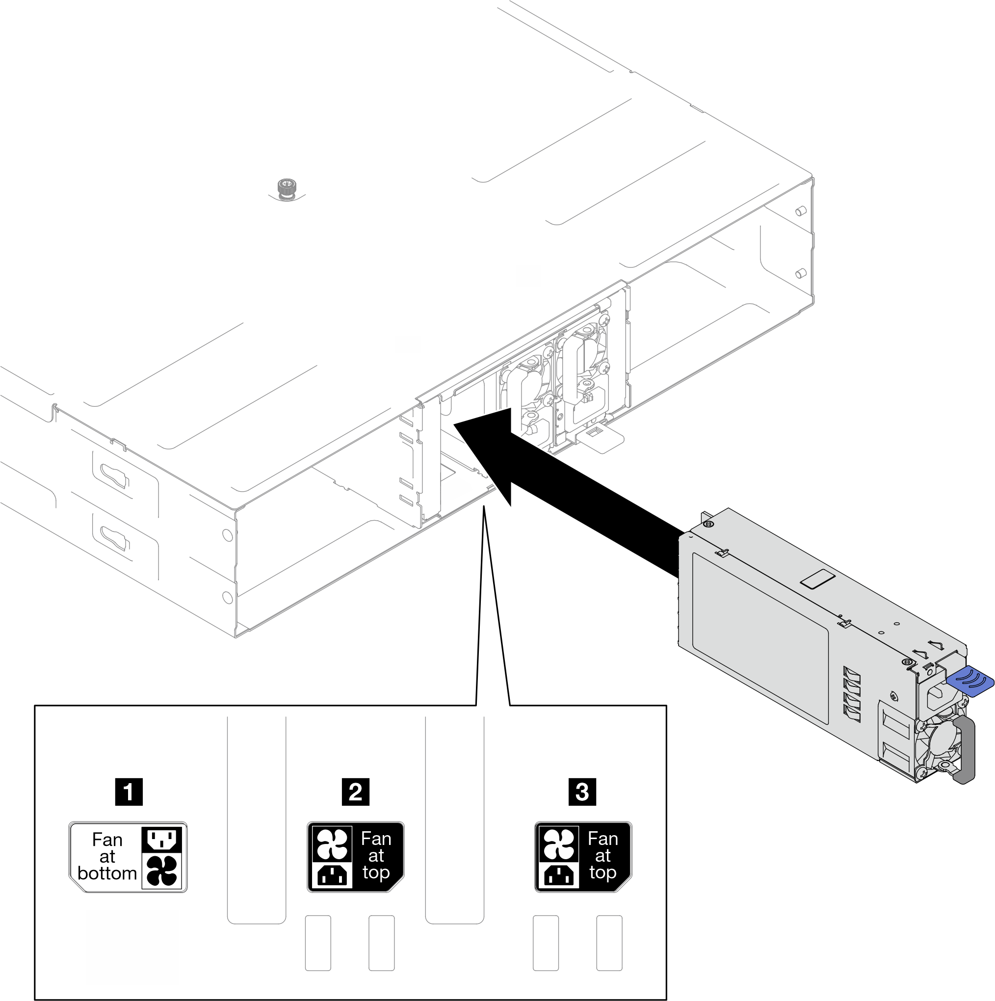
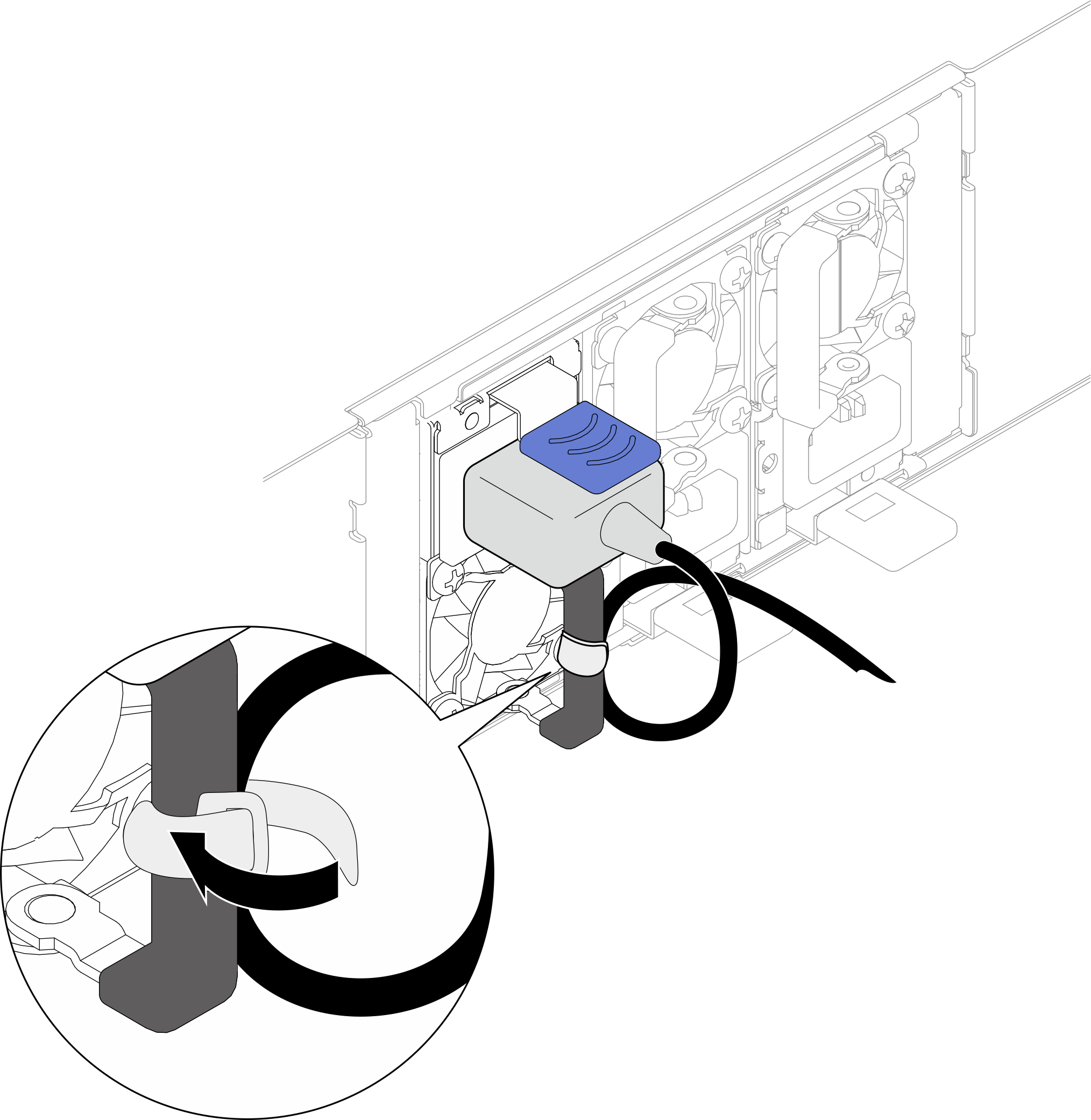
- Make sure the power supply unit handle is perpendicular to the power supply unit; then, tie the power cord to the handle with the pre-attached strap as shown below.Figure 3. Routing and tying power cord
After you finish
Make sure that the power LED on the power supply is lit, indicating that the power supply is operating correctly.
Demo video