
Install the drive cage assembly

Use this information to install the drive cage assembly.

About this task
Attention
Read the Installation Guidelines to ensure that you work safely.

Procedure

  1. Install the SATA or NVMe spacer into the compute node tray based on the type of drive(s) you will install into the drive cage assembly (see Replace SATA and NVMe spacers).
  2. Follow the corresponding procedures to install a 7mm or 15mm drive cage assembly.

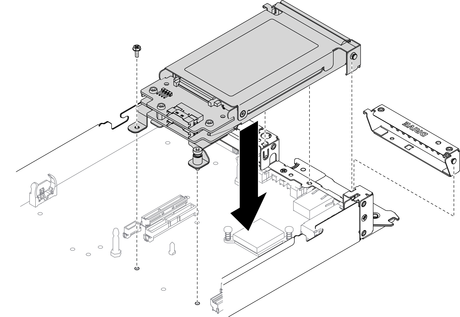
    Install a 7mm drive cage assembly:

    1. Align the hook and guide pin on the rear end of the drive cage assembly with the notches on the SATA/NVMe spacer and on the compute node tray as illustrated. Then, lower the drive cage assembly into the tray until the hook and guide pin are secured in place.
      Important
      During normal operation, the drive bay must contain either a drive cage assembly or drive bay filler for proper cooling.
    2. Fasten the screw on the left and tighten the captive screw on the right to secure the drive cage assembly to the compute node tray.
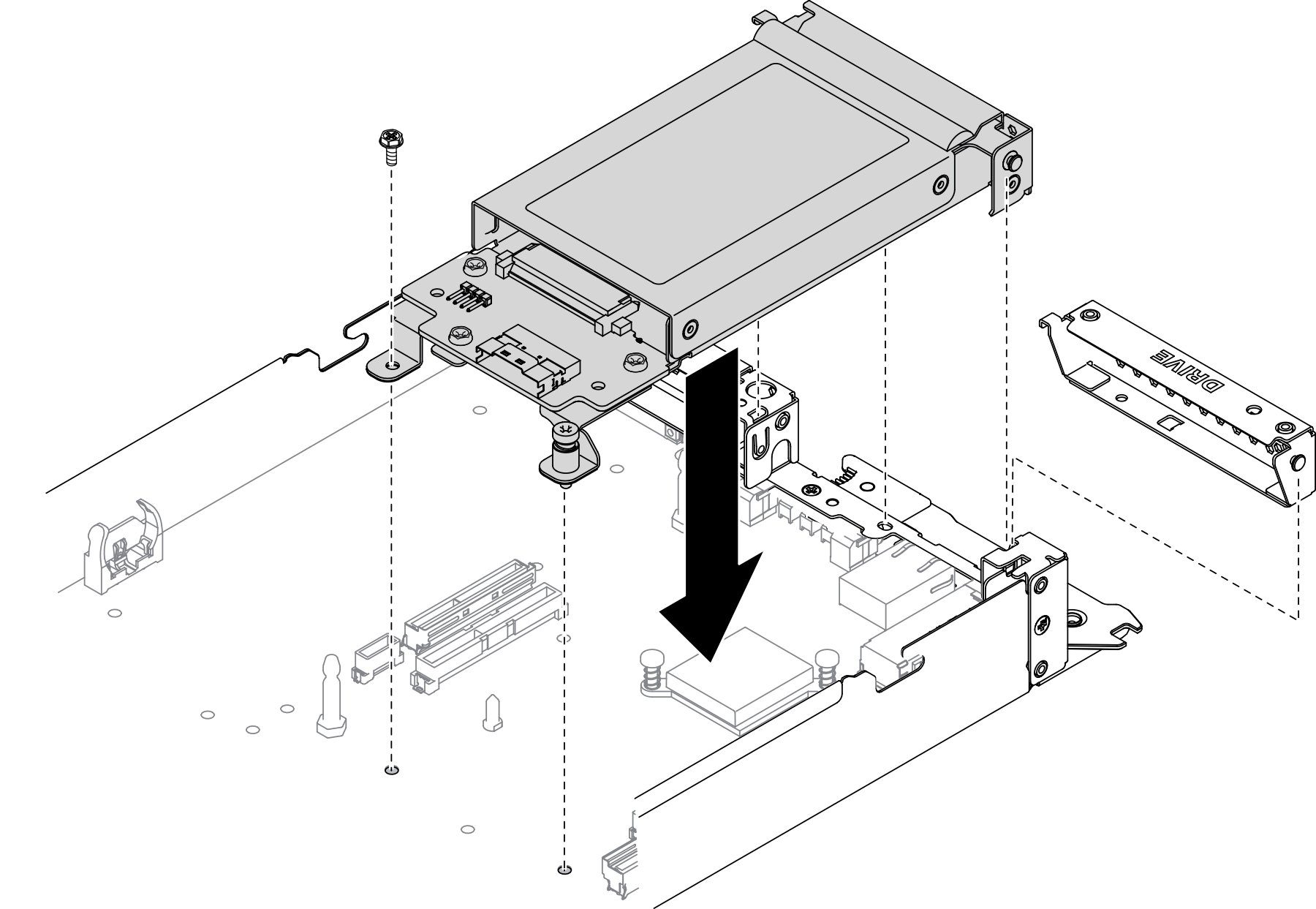
    3. Reconnect the cable connecting the system board and drive backplanes (see 7mm 2.5-inch SATA/NVMe drive backplane cable).
      Figure 1. 7mm drive cage assembly installation
      7mm drive cage assembly installation

    Install a 15mm drive cage assembly:

    1. Align the hook and guide pin on the rear end of the drive cage assembly with the notches on the NVMe spacer and on the compute node tray as illustrated. Then, lower the drive cage assembly into the tray until the hook and guide pin are secured in place.
      Important
      During normal operation, the drive bay must contain either a drive cage assembly or drive cage filler panel for proper cooling.
    2. Fasten the screw on the left and tighten the captive screw on the right to secure the drive cage assembly to the compute node tray.
    3. Reconnect the cable connecting the system board and drive backplane (see 15mm 2.5-inch NVMe drive backplane cable).
      Figure 2. 15mm drive cage assembly installation
      15mm drive cage assembly installation

After you finish

  1. Reinstall the components listed below into the compute node in the following order:
    1. Drive(s) (see Install a hot-swap solid-state drive).

    2. Node front cover (see Install the node front cover).

  2. Reinstall the compute node into the enclosure (see Install a compute node in the enclosure).

  3. Check the power LED on each node to make sure it changes from fast blink to slow blink to indicate the node is ready to be powered on.

Demo video

Watch the procedure on YouTube