Compute node
The following illustration shows the controls, LEDs, and connectors on the front of the compute node.
Configuration with two 7mm 2.5-inch SATA/NVMe SSDs and PCIe riser
See the following illustration for components, connectors, drive bay and PCIe slot numbering in the configuration with two 7mm 2.5-inch SATA/NVMe SSDs and a PCIe riser.
Figure 1. Configuration with two 7mm 2.5-inch SATA/NVMe SSDs and PCIe riser
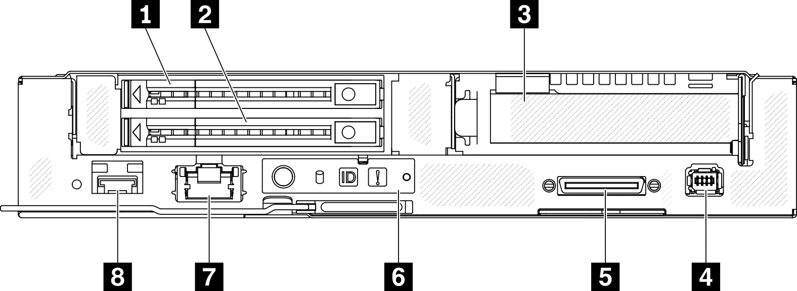
| 1 7mm 2.5-inch SATA/NVMe SSD bay 1 | 5 USB 3.0 Console Breakout Cable connector |
| 2 7mm 2.5-inch SATA/NVMe SSD bay 0 | 6 Node operator panel |
| 3 PCIe slot 1 | 7 1 Gb RJ45 Ethernet port with share-NIC feature for Lenovo XClarity Controller * |
| 4 External diagnostics connector | 8 25 Gb SFP28 Ethernet port with share-NIC feature for Lenovo XClarity Controller * |
Note
* Lenovo XClarity Controller can be accessed by either RJ45 Ethernet port or SFP28 Ethernet port.
Configuration with 15mm 2.5-inch NVMe SSD and PCIe riser
See the following illustration for components, connectors, drive bay and PCIe slot numbering in the configuration with a 15mm 2.5-inch NVMe SSD and a PCIe riser.
Figure 2. Configuration with 15mm 2.5-inch NVMe SSD and PCIe riser
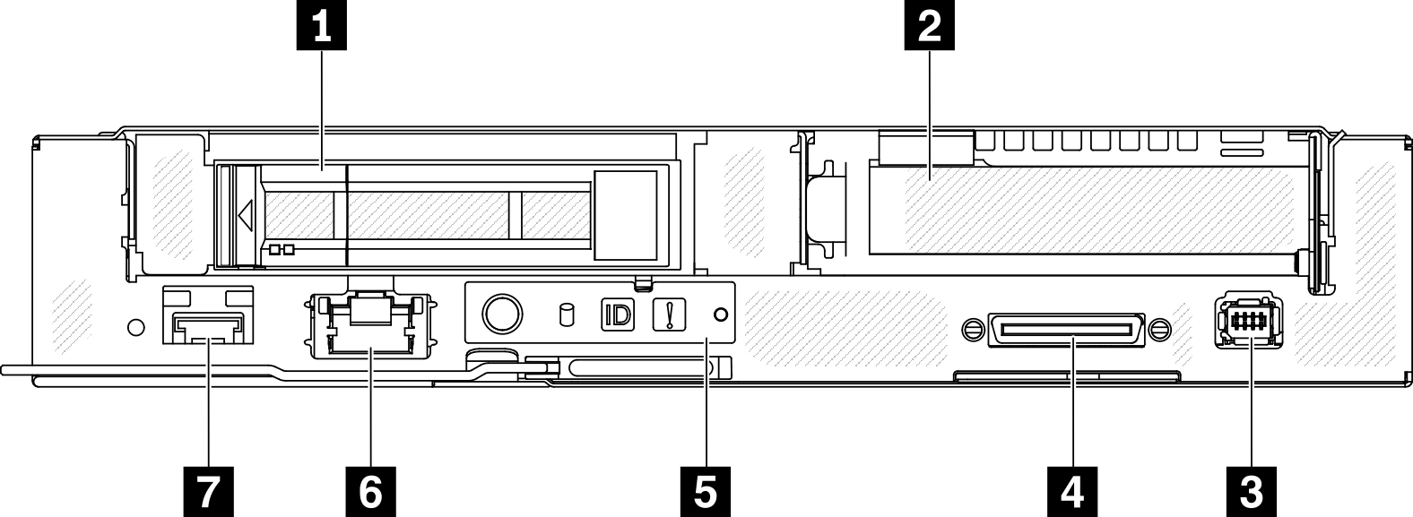
| 1 15mm 2.5-inch NVMe SSD bay | 5 Node operator panel |
| 2 PCIe slot 1 | 6 1 Gb RJ45 Ethernet port with share-NIC feature for Lenovo XClarity Controller * |
| 3 External diagnostics connector | 7 25 Gb SFP28 Ethernet port with share-NIC feature for Lenovo XClarity Controller * |
| 4 USB 3.0 Console Breakout Cable connector |
Note
* Lenovo XClarity Controller can be accessed by either RJ45 Ethernet port or SFP28 Ethernet port.
Give documentation feedback