Front LEDs and buttons
The following illustration shows LEDs and buttons on the front of the compute node.
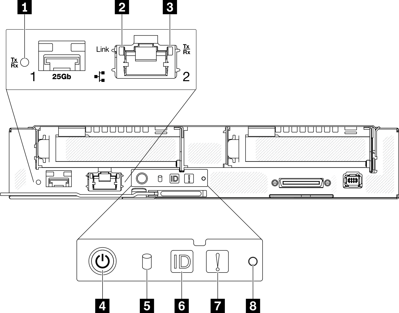
| 1 25 Gb SFP28 Ethernet port link and activity LED (green) | 5 M.2 drive activity LED (green) |
| 2 1 Gb RJ45 Ethernet port link LED (green) | 6 Identification button / LED (blue) |
| 3 1 Gb RJ45 Ethernet port activity LED (green) | 7 System error LED (yellow) |
| 4 Node power button / LED (green) | 8 NMI pinhole |
1 25 Gb SFP28 Ethernet port link and activity LED (green): Use this green LED to distinguish the network status.
- Off: The network is disconnected.
- Blinking: The network is accessing.
- On: The network is established.
2 1 Gb RJ45 Ethernet port link LED (green): Use this green LED to distinguish the network status.
- Off: The network link is disconnected.
- On: The network link is established.
3 1 Gb RJ45 Ethernet port activity LED (green): Use this green LED to distinguish the network status.
- Off: The node is disconnected from a LAN.
- Blinking: The network is connected and active.
- Off: Power is not present; the power supply or the LED itself has failed.
- Flashing rapidly (4 times per second): The compute node is turned off and is not ready to be turned on. The power button is disabled. This will last approximately 5 to 10 seconds.
- Flashing slowly (once per second): The compute node is turned off, connected to power through the enclosure and ready to be turned on. You can press the power button to turn on the node.
- On: The compute node is turned on and connected to power through the enclosure.
For SATA SSDs, this LED is on when the SSD is powered; when this LED is flashing, it indicates that the drive is actively reading or writing data.
For NVMe SSDs, this LED is on solid when the SSD is powered and when the SSD is actively reading or writing data.
| SMM2 identification LED | Node identification LEDs |
| Off | When this option is activated, SMM2 ID LED would first turn off the ID LED on all the compute nodes in the enclosure and enter the accept mode, in which the LED behavior is determined by the node ID LEDs (see Enclosure Rear Overview for more information). |
| On | All of the node ID LEDs will be on except the blinking ones, which will remain blinking. |
| Blink | All of the node ID LEDs will be blinking regardless of previous status. |
7 System error LED (yellow): When this LED (yellow) is lit, it indicates that at least one system error has occurred. Check the event log for additional information.
8 NMI pinhole: Insert the tip of a straightened paper clip into this pinhole to force a non-maskable interrupt (NMI) upon the node, and consequent memory dump would take place. Only use this function while advised by Lenovo support representative.