System Management Module 2 (SMM2)
The following illustration shows the connectors and LEDs on the rear of the System Management Module 2 (SMM2).
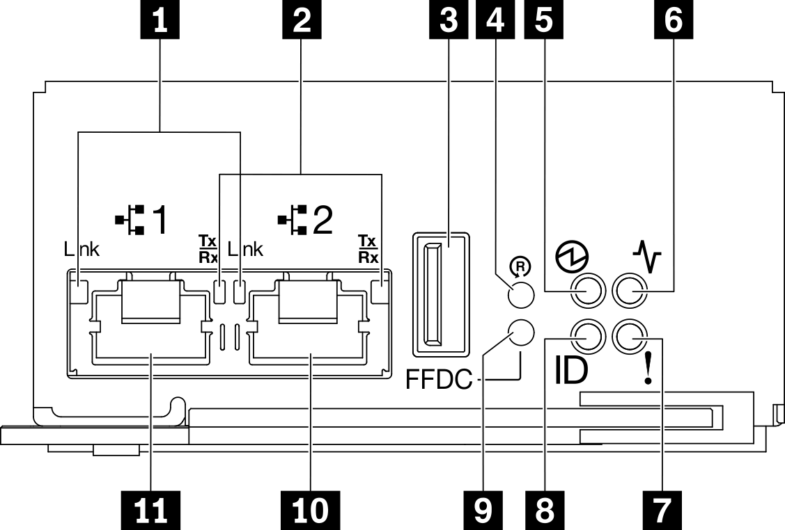
| 1 Ethernet port 1 and port 2 link (RJ-45) LED (green) | 7 Check log LED (yellow) |
| 2 Ethernet port 1 and port 2 activity (RJ-45) LED (green) | 8 Identification LED (blue) |
| 3 USB connector | 9 USB port service mode button |
| 4 Reset pinhole | 10 Ethernet port 2 |
| 5 Power LED (green) | 11 Ethernet port 1 |
| 6 Status LED (green) |
1 Ethernet port 1 and port 2 link (RJ-45) LED (green): When this LED is lit (green), it indicates that there is an active connection through the remote management and console (Ethernet) port 1 and port 2 to the management network.
2 Ethernet port 1 and port 2 activity (RJ-45) LED (green): When this LED is flashing (green), it indicates that there is an activity through the remote management and console (Ethernet) port 1 and port 2 over the management network.
3 USB connector: Insert the USB storage device to this connector and then press the USB port service mode button to collect FFDC logs.
4 Reset pinhole: Press the button for one to four seconds, SMM2 reboots. Press over four seconds, SMM2 reboots and loads to the default settings.
5 Power LED: When this LED is lit (green), it indicates that the SMM2 has power.
Continuously on: The SMM2 has encountered one or more problems.
Off: When the enclosure power is on, it indicates the SMM2 has encountered one or more problems.
- Flashing: The SMM2 is working.
During the pre-boot process, the LED flashes rapidly.
Ten times per second: The SMM2 hardware is working and the firmware is ready to initialize.
Two times per second: The firmware is initializing.
When the pre-boot process is completed and the SMM2 is working correctly, the LED flashes at a slower speed (about once every two seconds).
7 Check log LED: When this LED is lit (yellow), it indicates that a system error has occurred. Check the SMM2 event log for additional information.
8 Identification LED: When this LED is lit (blue), it indicates the enclosure location in a rack.
9 USB port service mode button: Press this button to collect FFDC logs after inserting the USB storage device to the USB connector.
10 Ethernet port 2: Use this connector to access SMM2 management.
11 Ethernet port 1: Use this connector to access SMM2 management.