Remove a GPU OAM
Use this information to remove a GPU OAM. This procedure is trained technician only.
About this task
Required tools
Make sure you have the required tools listed below in hand to properly replace the component.
Water loop kits
SD650-I V3 Water loop service kit (03KH870)
SD650-I V3 Water loop putty pad kit (03LD670)
Screws and screwdrivers
Prepare the following screwdrivers to ensure you can install and remove corresponding screws properly.Screwdriver Type Screw Type Torx T10 head screwdriver Torx T10 screw Phillips #1 head screwdriver Phillips #1 screw Phillips #2 head screwdriver Phillips #2 screw
Read Installation Guidelines and Safety inspection checklist to ensure that you work safely.
Turn off the corresponding DWC tray that you are going to perform the task on.
Disconnect all external cables from the enclosure.
Use extra force to disconnect QSFP cables if they are connected to the solution.
To avoid damaging the water loop, always use the water loop carrier when removing, installing or folding the water loop.
Procedure
- Remove the following screws to loosen the quick connect.
Two Torx T10 screws to loosen the quick connect.
Four Torx T10 screws on the rear of the node.
Figure 2. Quick connect screw removal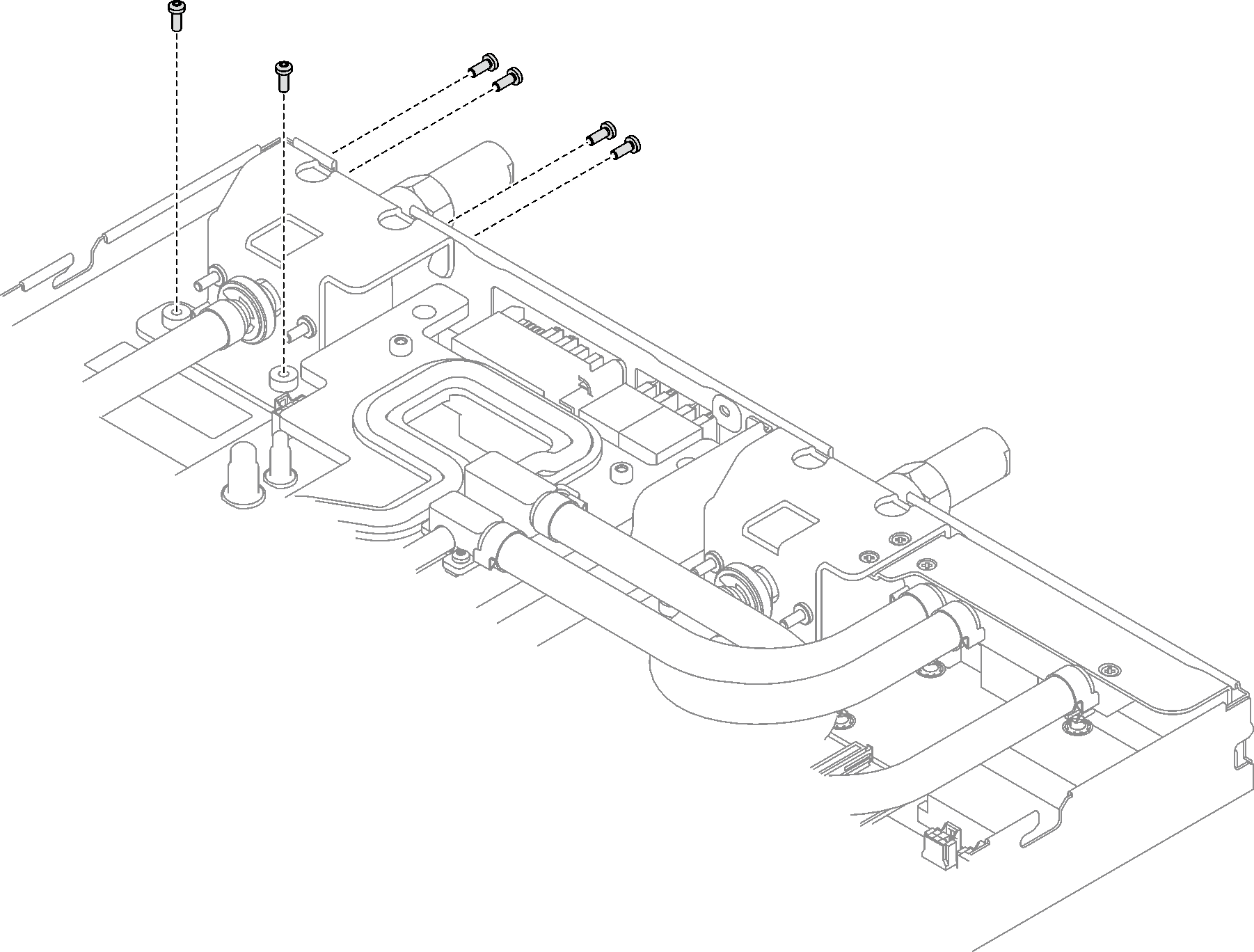
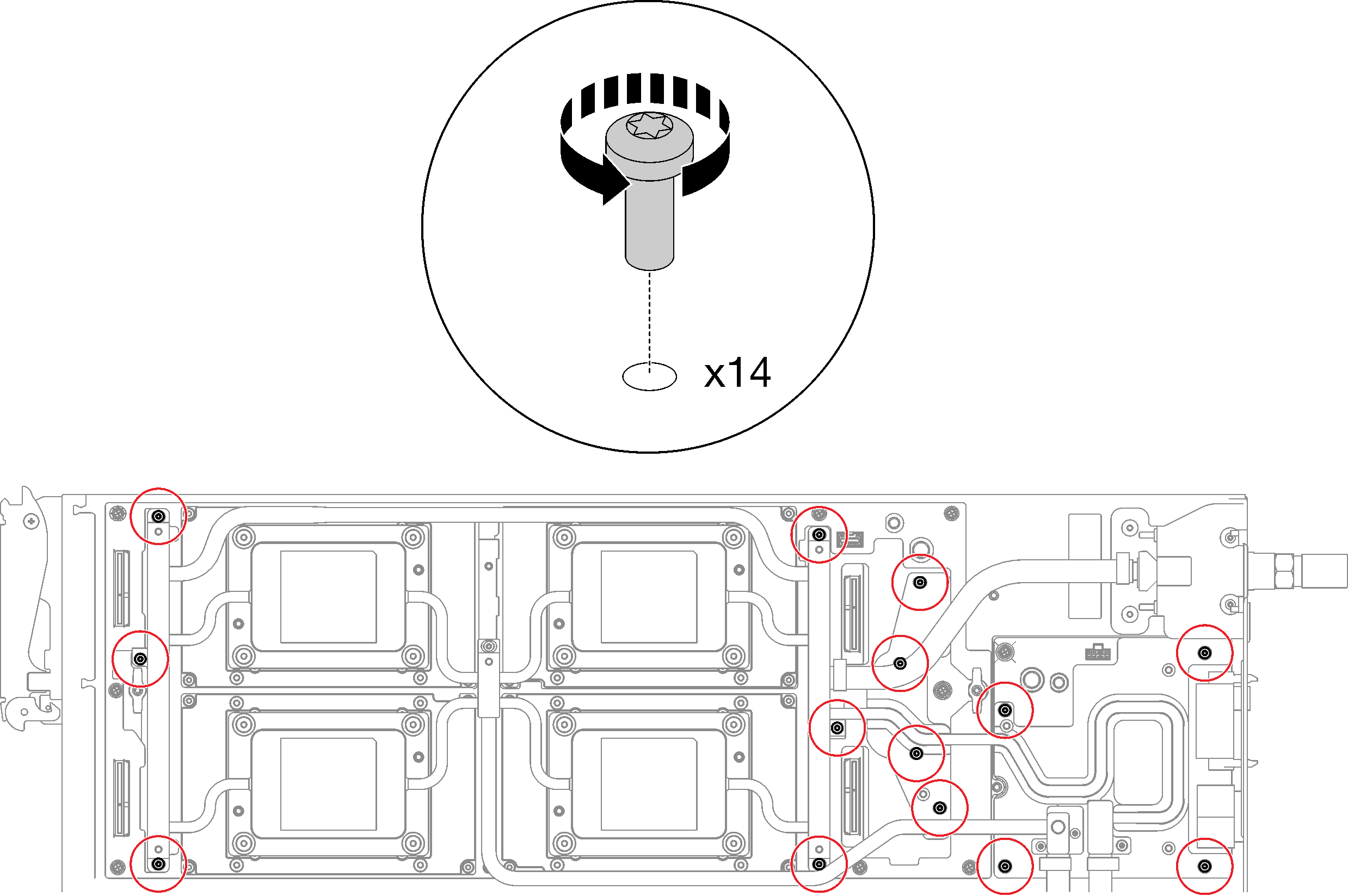
- Remove fourteen Torx T10 water loop screws with a torque screwdriver set to the proper torque.NoteFor reference, the torque required for the screws to be fully tightened/removed is 5.0+/- 0.5 lbf-in, 0.55+/- 0.05 N-M.Figure 3. Water loop screws removal
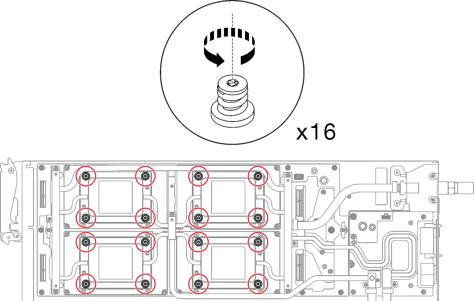
- Remove GPU OAM cold plate screws (16x Torx T15 screws) with a torque screwdriver set to the proper torque.NoteFor reference, the torque required for the screws to be fully tightened/removed is 0.9 +/-0.06 newton-meters, 8+/- 0.5 inch-pounds. The rpm setting is 200 rpm low-speed.Figure 4. GPU OAM cold plate screws removal
- Release the interface plate with a flat head screwdriver.
- There are two notches on the sides of each GPU OAM cold plate for inserting a flat head screwdriver—select the one that is accessible for the flat head screwdriver.Figure 5. Notches on GPU OAM cold plate
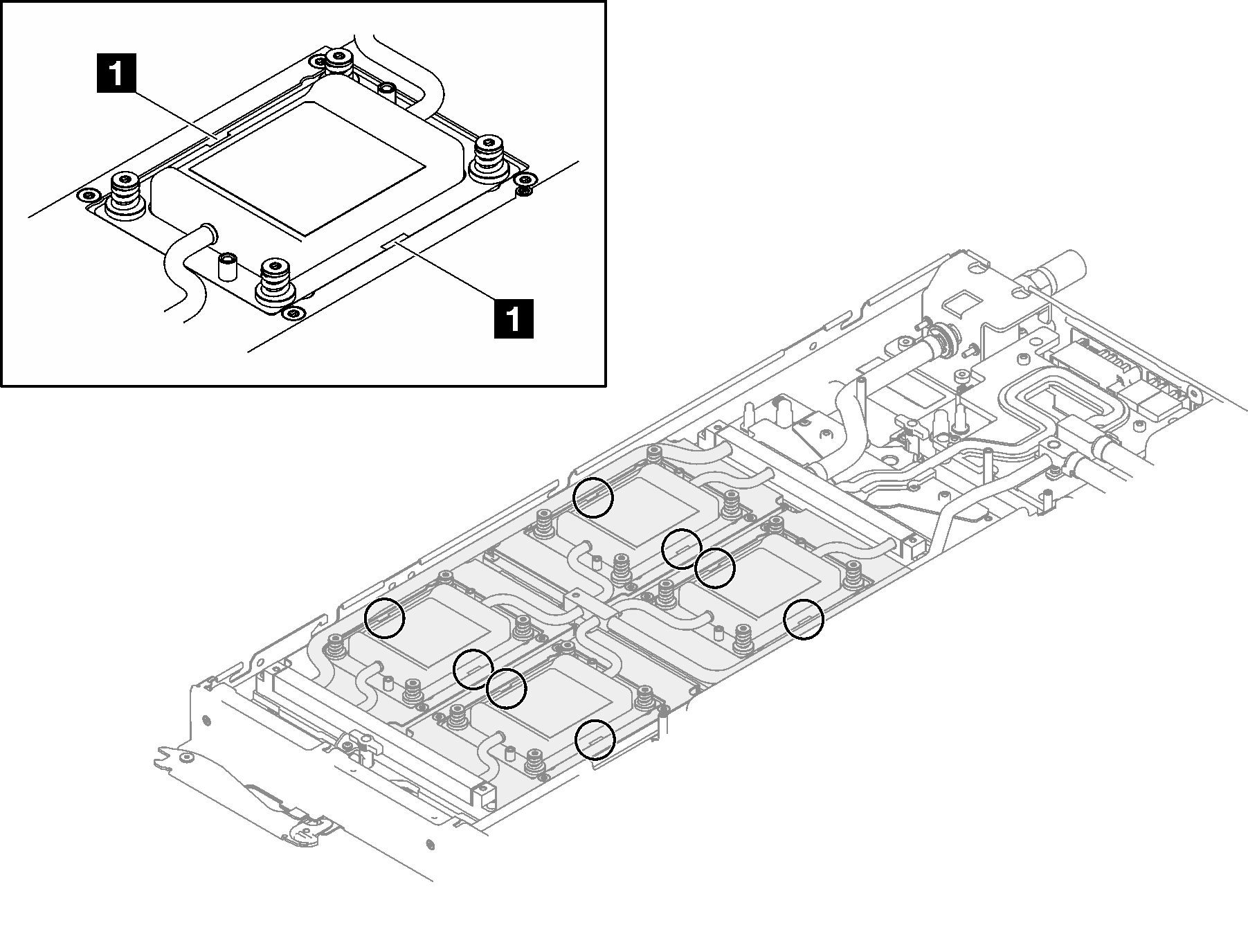
1 Notches - Perform Step B on every GPU OAM cold plate to make sure they are all released from GPU OAM.Figure 6. Release the GPU OAM cold plate from the GPU OAM
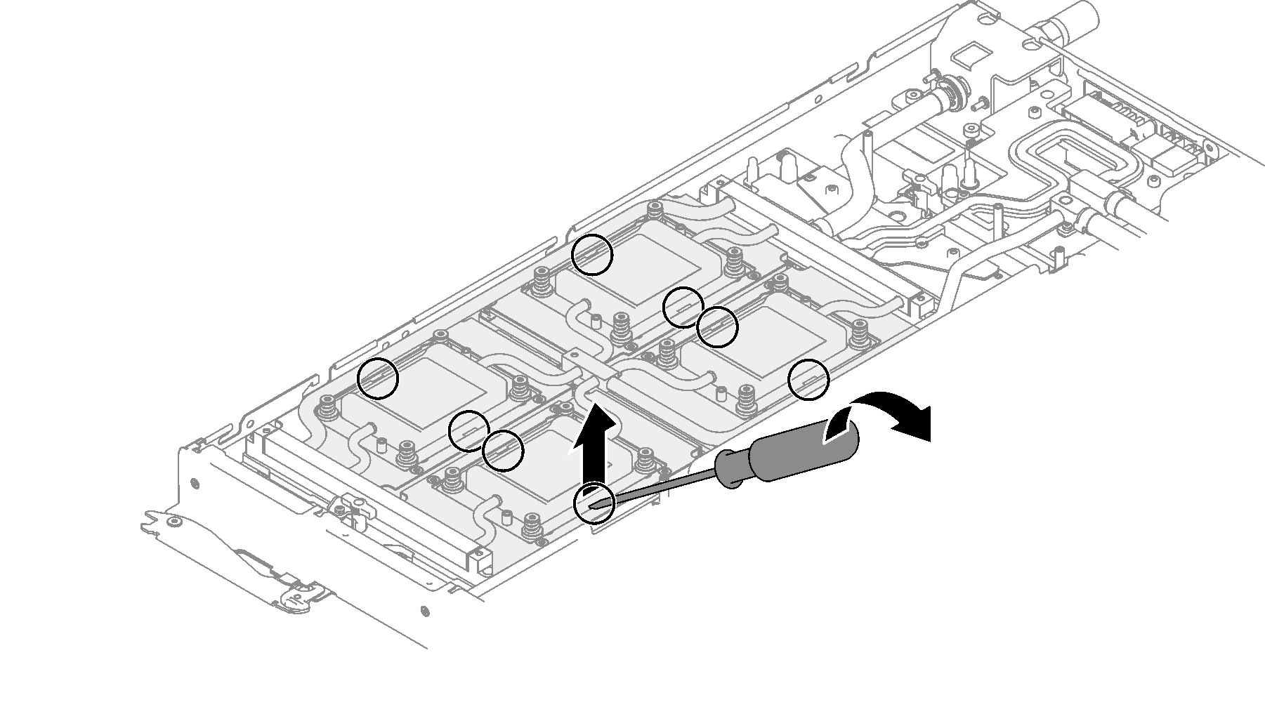
- There are two notches on the sides of each GPU OAM cold plate for inserting a flat head screwdriver—select the one that is accessible for the flat head screwdriver.
- From the front and the rear of the GPU node, find the gaps between the retimer tank on water loop and the carrier base board conduction plate, as shown in the following illustrations. Then, insert the flat head screwdriver into the gaps, and slightly rotate screwdriver to release the two components.Figure 7. Separating water loop retimer tank from carrier base board conduction plate – GPU node front
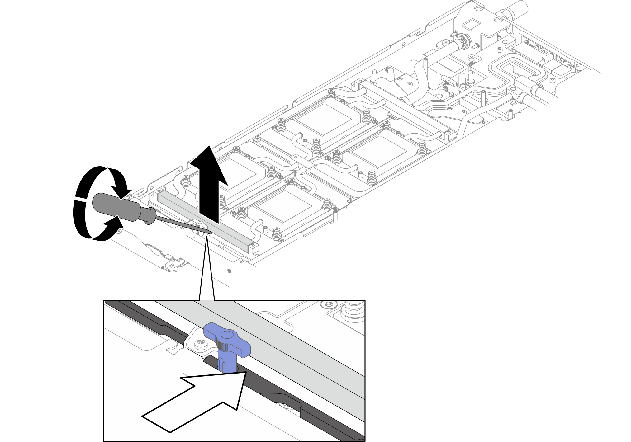 Figure 8. Separating water loop retimer tank from carrier base board conduction plate – GPU node rear
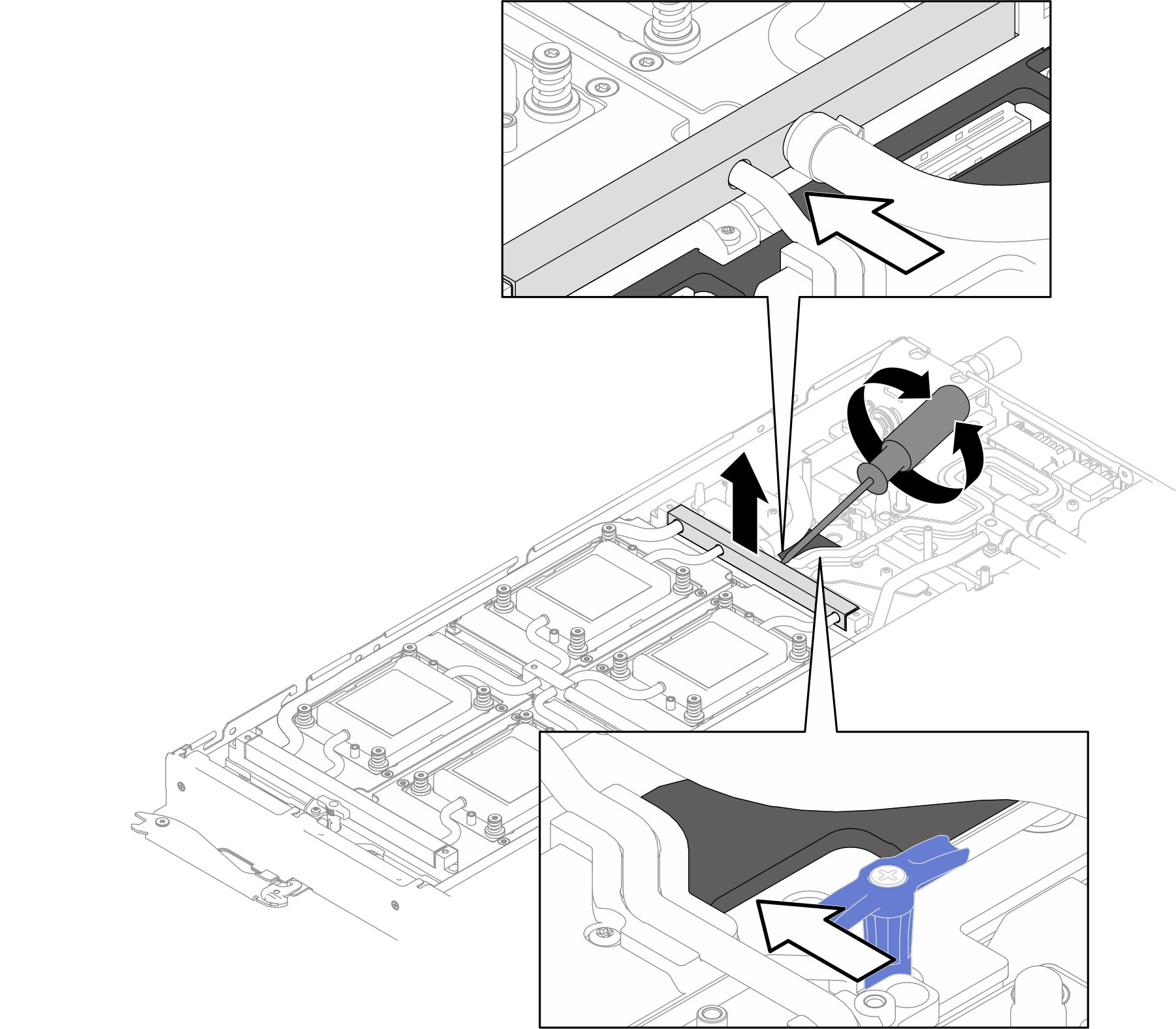
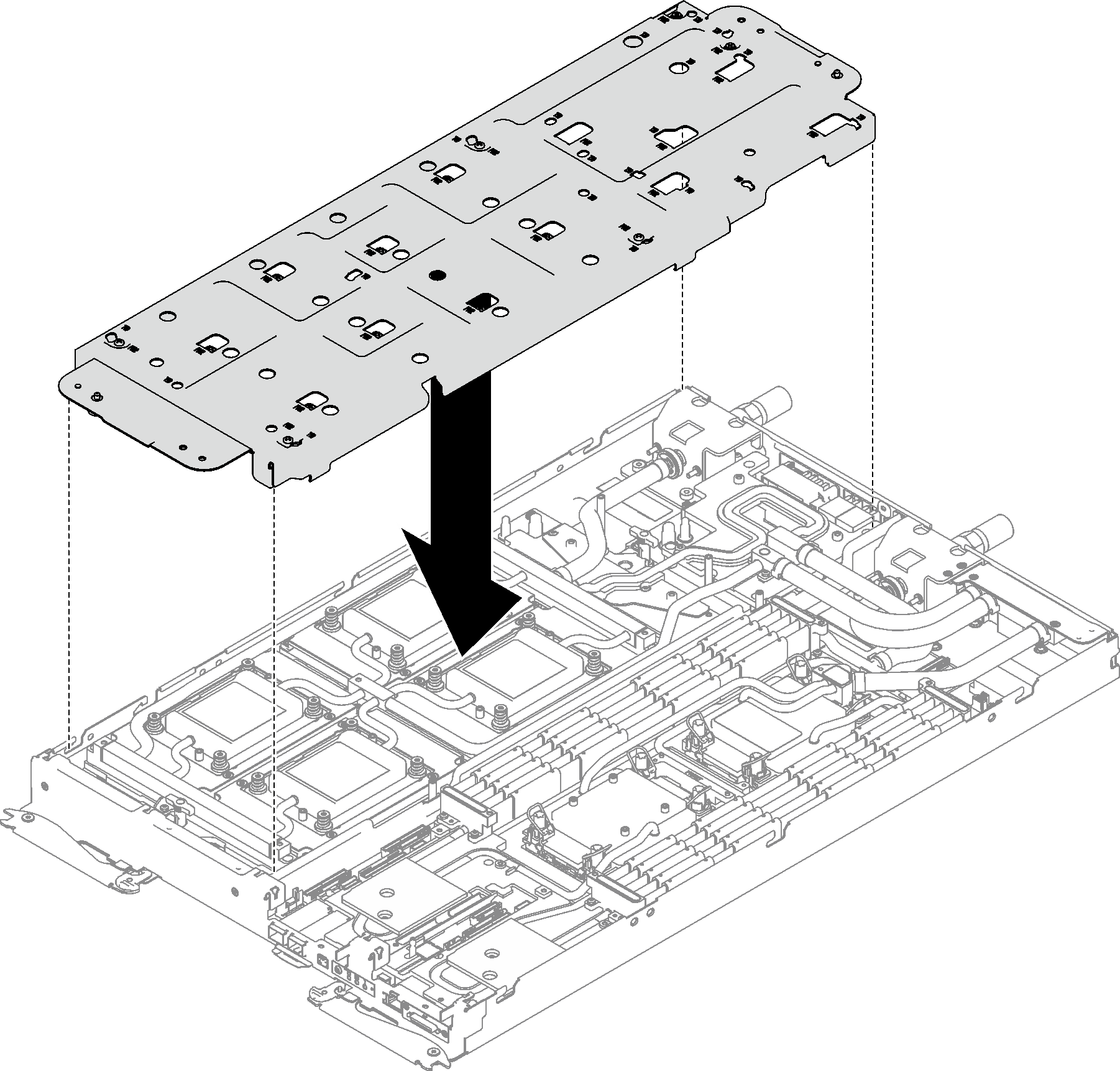
- Orient the water loop carrier with the slots; then, gently put the water loop carrier down and ensure it is seated firmly on the water loop.Figure 9. Water loop carrier installation
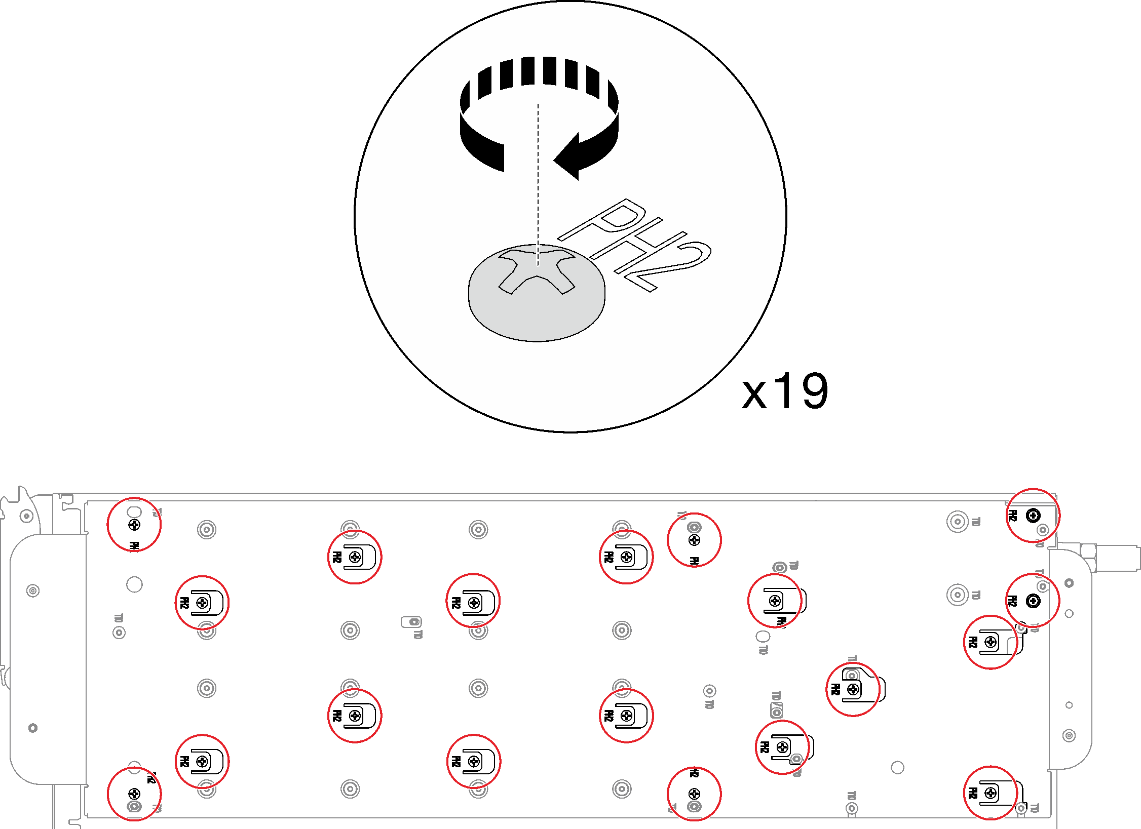
- Tighten water loop carrier screws (19x Phillips #2 screws).Figure 10. Water loop carrier screws installation
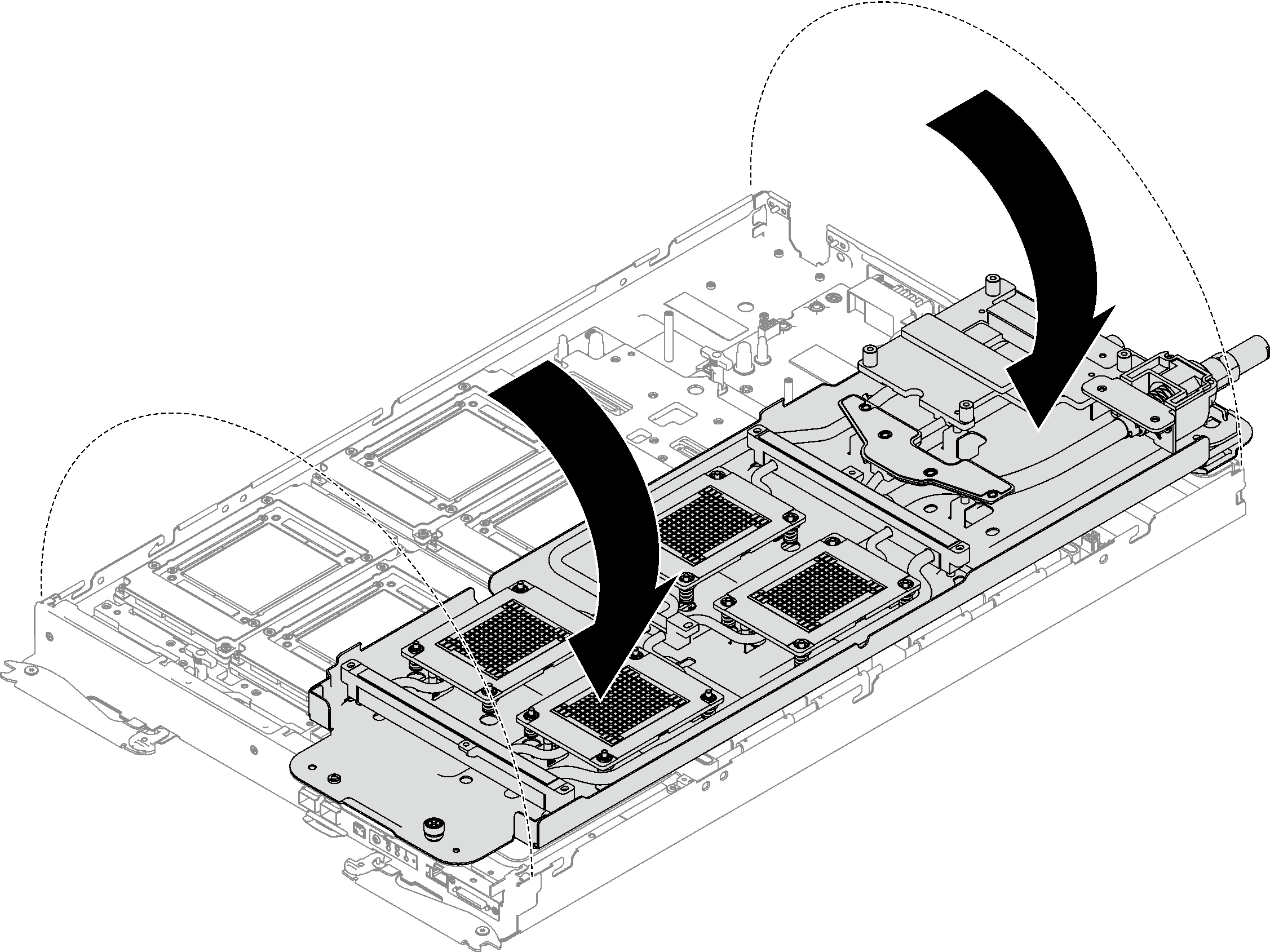
- Carefully rotate the water loop so one half is sitting on top of the other half.Figure 11. Folding the water loop
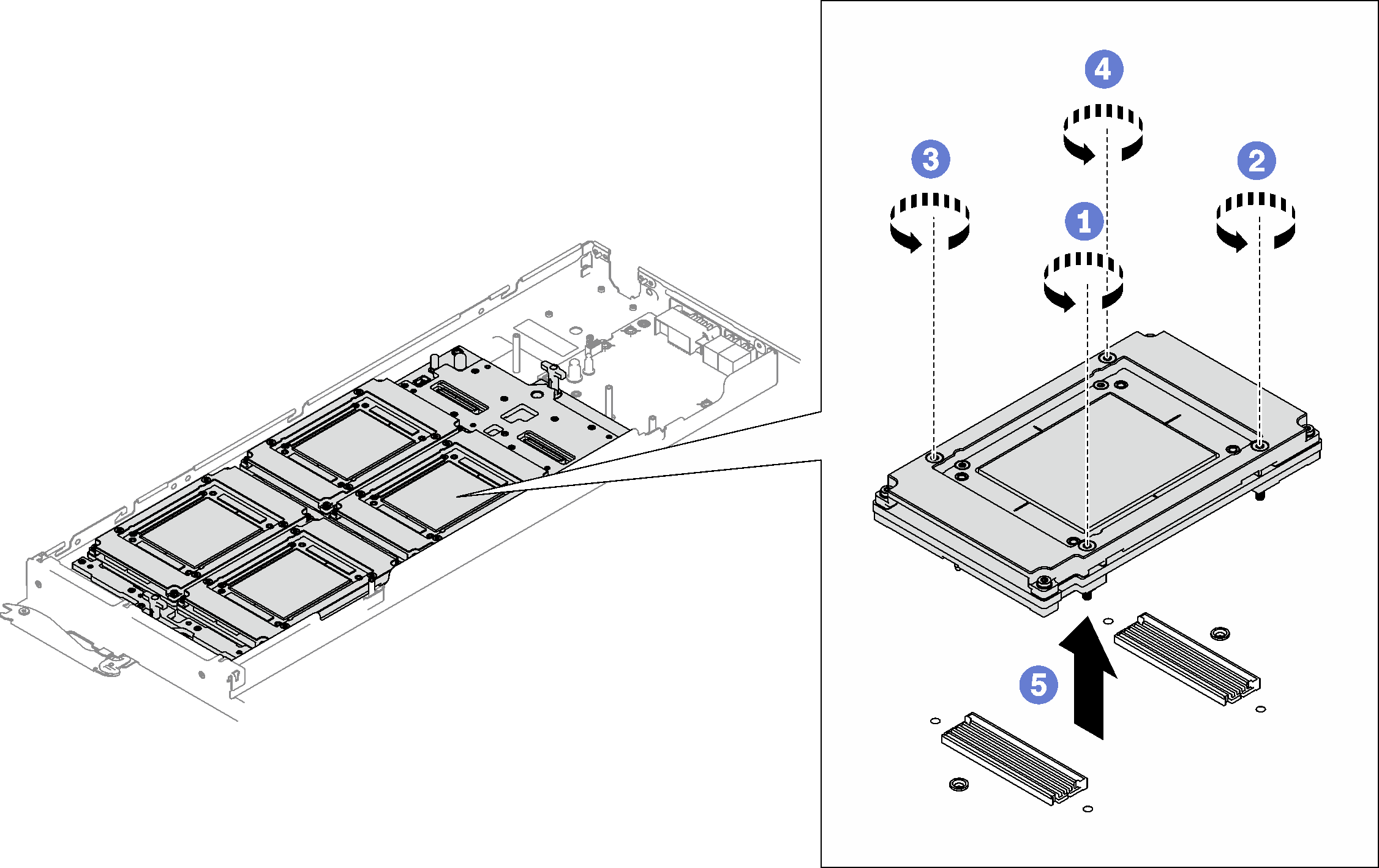
- Locate the GPU OAM which should be removed; then, remove the four Torx T15 screws (with a torque screwdriver set to the proper torque) and carefully remove the GPU OAM out of the carrier base board (CBB).NoteFor reference, the torque required for the screws to be fully tightened/removed is 9kgf.cm (7.8 lbf.in).Figure 12. GPU OAM removal
If you are instructed to return the component or optional device, follow all packaging instructions, and use any packaging materials for shipping that are supplied to you.