Front LEDs
The following illustration shows LEDs on the front of the solution. By viewing the status of LEDs, you can often identify the source of the error.
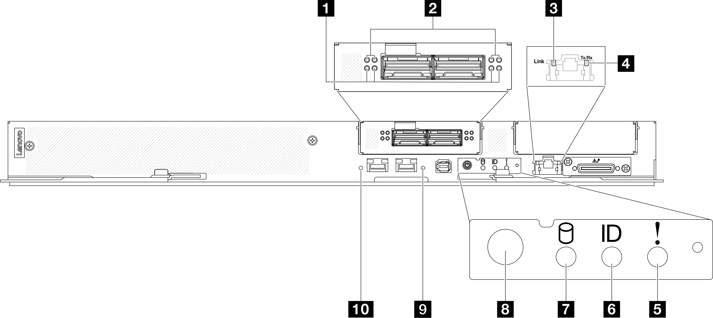
| 1 Network board link activity LED (green) on the OSFP module | 6 Identification LED (blue) |
| 2 Network board link status LED (yellow) on the OSFP module | 7 Drive activity LED (green) |
| 3 1 Gb Ethernet port activity LED (green) | 8 Node power button with LED (green) |
| 4 1 Gb Ethernet port link LED (green) | 9 25 Gb Ethernet port link and activity LED (right) (green) |
| 5 Check log LED (yellow) | 10 25 Gb Ethernet port link and activity LED (left) (green) |
For one-processor configuration: from left to right, these LEDs represent ConnectX-7 chip sets 0, 1, 3, and 2.
For two-processor configuration: from left to right, these LEDs represent ConnectX-7 chip sets 1, 0, 3, and 2.
- Off: Network is disconnected from switch.
- Blinking: The network link is connected and active.
For one-processor configuration: from left to right, these LEDs represent ConnectX-7 chip sets 0, 1, 3, and 2.
For two-processor configuration: from left to right, these LEDs represent ConnectX-7 chip sets 1, 0, 3, and 2.
- Off: Network is disconnected from switch.
- On: The network is connected and active.
3 1 Gb Ethernet port activity LED (green): Use this green LED to distinguish the network status.
- Off: The ConnectX-7 chip sets link is disconnected.
- On: The ConnectX-7 chip sets link is established.
4 1 Gb Ethernet port link LED (green): Use this green LED to distinguish the network status.
- Off: The network link is disconnected.
- On: The network link is established.
5 Check log LED (yellow): When this yellow LED is lit, it indicates that a system error has occurred. Check the XCC event log for additional information.
6 Identification LED (blue): Use this blue LED to visually locate the node among other nodes. This LED is also used as a presence detection button. You can use Lenovo XClarity Administrator to light this LED remotely.
7 Drive activity LED (green): If the LED is lit, it indicates that the drive is powered, but not actively reading or writing data. If the LED is flashing, the drive is being accessed.
- Off: Power is not present or the power supply, or the LED itself has failed.
- Flashing rapidly (4 times per second): The node is turned off and is not ready to be turned on. The power button is disabled. This will last approximately 5 to 10 seconds.
- Flashing slowly (once per second): The node is turned off and is ready to be turned on. You can press the power button to turn on the node.
- On: The node is turned on.
9 10 25 Gb Ethernet port link and activity LED (green): Use this green LED to distinguish the network status.
- Off: The network is disconnected.
- Blinking: The network is accessing.
- On: The network is established.