Internal cable routing
Use this information to route the cables for one-processor and two-processor configurations.
Attention
Make sure the OSFP module is installed and all cables are connected to the network board.
Note
Disengage all latches, release tabs, or locks on cable connectors when you disconnect cables from the system board. Failing to release them before removing the cables will damage the cable sockets on the system board, which are fragile. Any damage to the cable sockets might require replacing the system board.
There are two cable ties on the GPU node. Unfasten the cable tie before removing the cables from the tray. After connecting the cables to the tray, bundle the cable tie to secure the cables.
Figure 1. Unfastening the cable tie 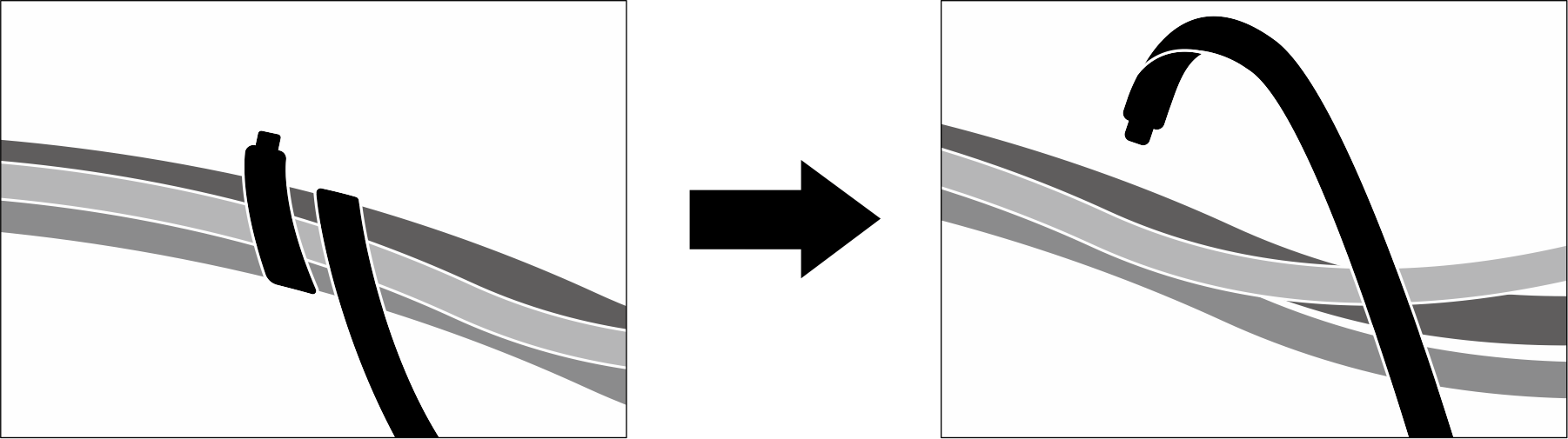 | Figure 2. Bundling the cable tie 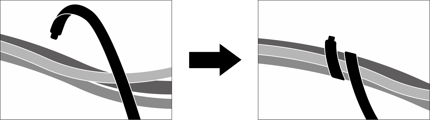 |
SD650-N V3 cable routing
Follow the information below for SD650-N V3 cable routing.
Connect the carrier board power and side band cable.
Figure 3. Carrier board power and side band cable routing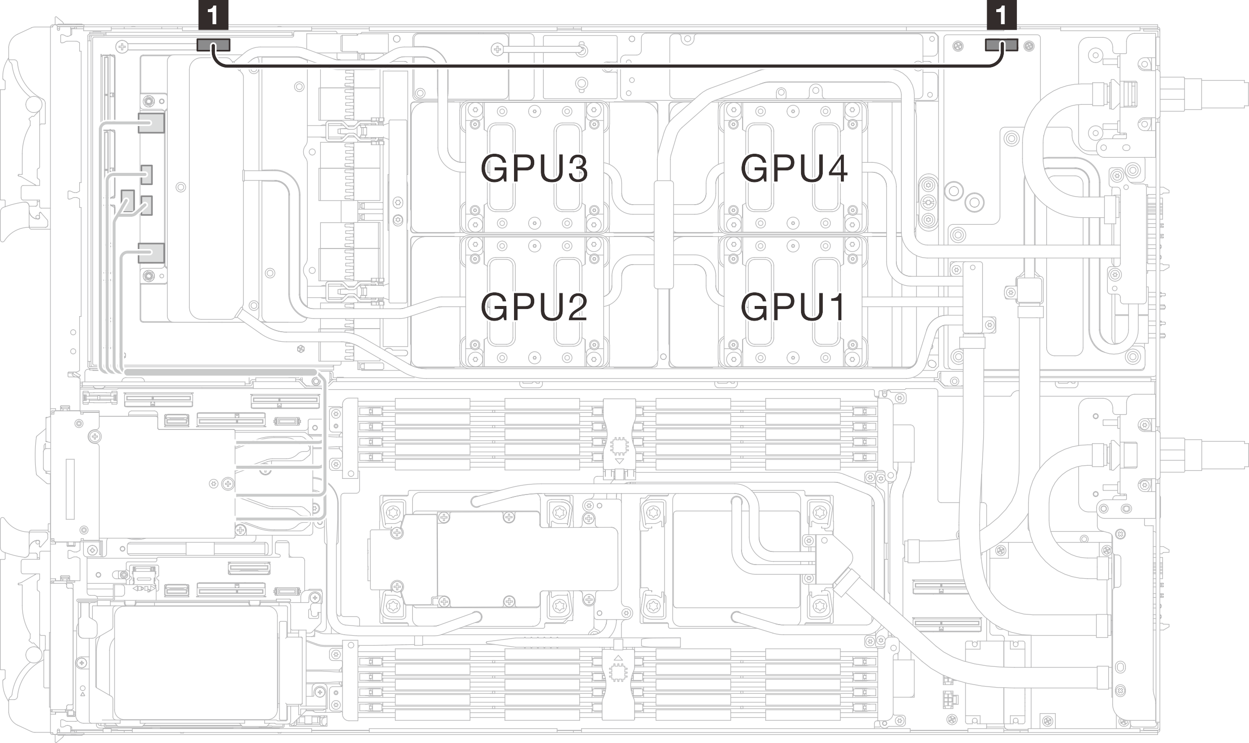
From To 1 Power and side band connector (on carrier board) 1 Power connector (on GPU node power distribution board) - Connect the MCIO cables from the GPU node to the Compute node.AttentionMake sure to follow the cable installation sequence:
1 → 2 → 3 → 4 Figure 4. MCIO cable routing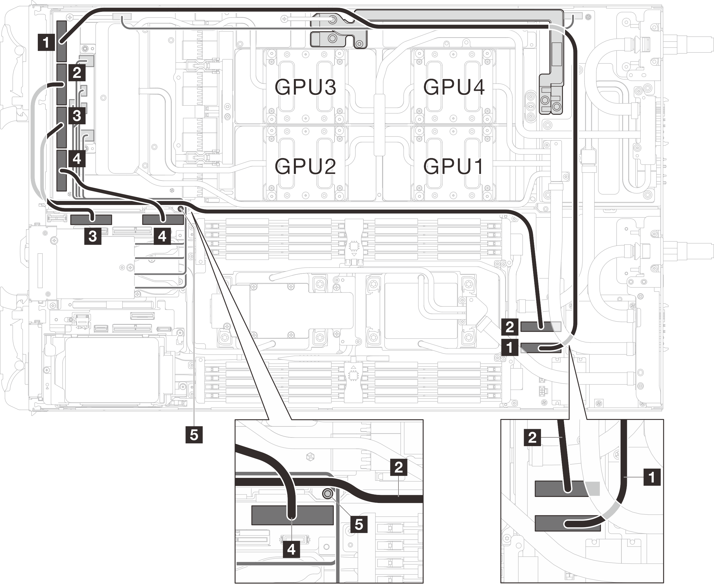
Table 1. SD650-N V3 cable routing From (carrier board) To (system board) 1 MCIO 1 1 PCIe x 16 MCIO 3 connector 2 MCIO 2 2 PCIe x 16 MCIO 4 connector 3 MCIO 3 3 PCIe x 16 MCIO 1 connector 4 MCIO 4 4 PCIe x 16 MCIO 2 connector 5 Stud (in between the nodes) Make sure the cables are routed around the stud as shown in the illustration. Bundle the cable ties (1) to secure the MCIO 1 cable and the carrier board power and side band cable.
Figure 5. Secure the cables with cable ties (1)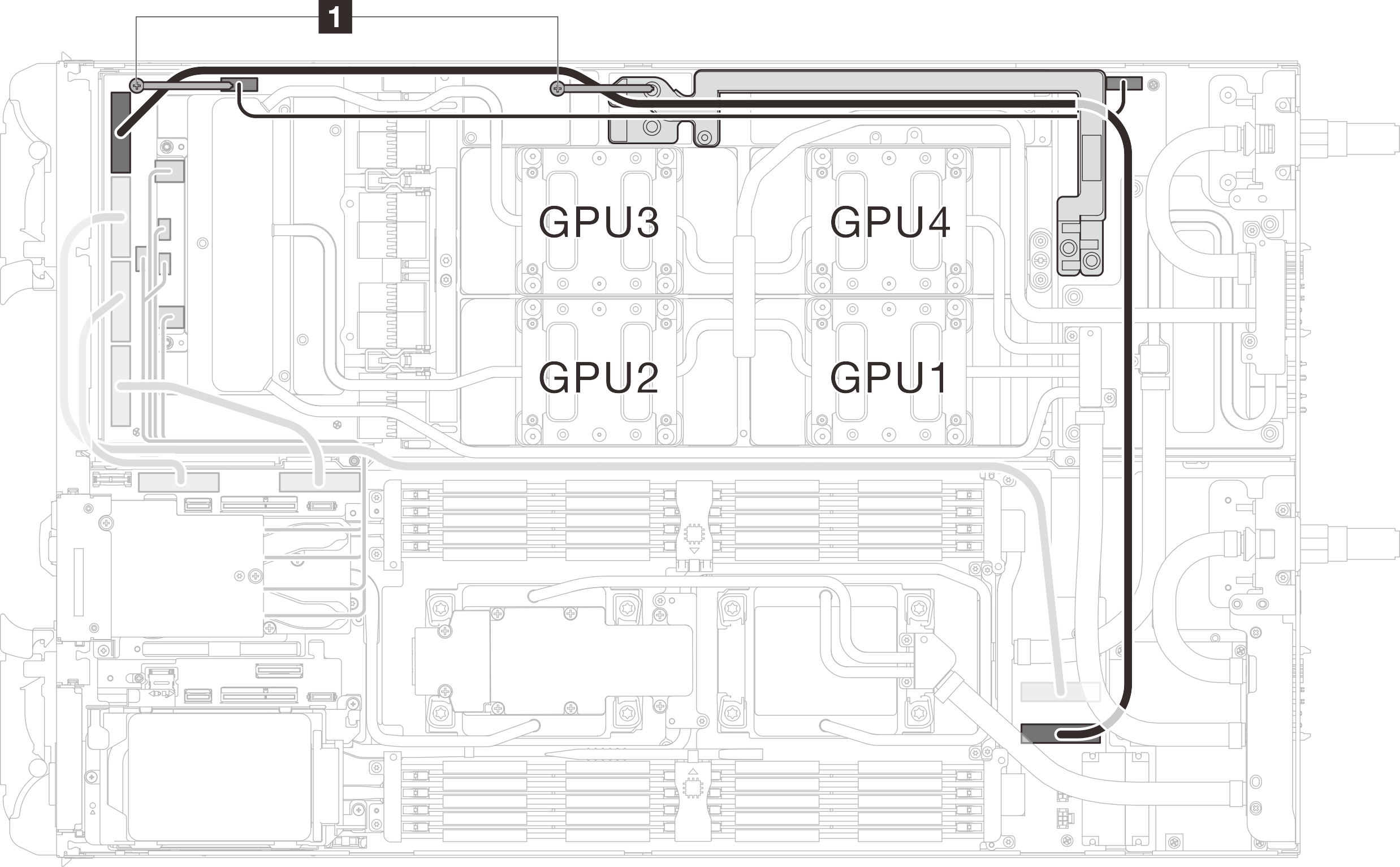
Give documentation feedback