Guidance on mixing trays configuration for the DW612S enclosure
Refer to the following section for more information on installing various direct water cooling trays into the DW612S enclosure.
DWC trays supported by the DW612S enclosure
SD650 V2
SD650-N V2
SD650 V3
SD650-I V3
SD650-N V3
SD665 V3
SD665-N V3
Mixing tray guidance
DW612S enclosure allows mixing trays configuration, which is installing different supporting trays in the same DW612S enclosure. Mixing trays configuration must meet the following requirements.
Enclosure total power consumption is reviewed and approved in Lenovo Capacity Planner website.
SMM2 is updated to the latest firmware.
If SD665-N V3 or SD650-N V3 is installed in the enclosure, only 2600W or 7200W PSUs are supported.
If SD650 V2 or SD650 V3 is installed in the enclosure and shared I/O configuration is enabled, the shared I/O special node power on/off sequence must be followed. See Shared I/O configuration specific power on and power off sequence.
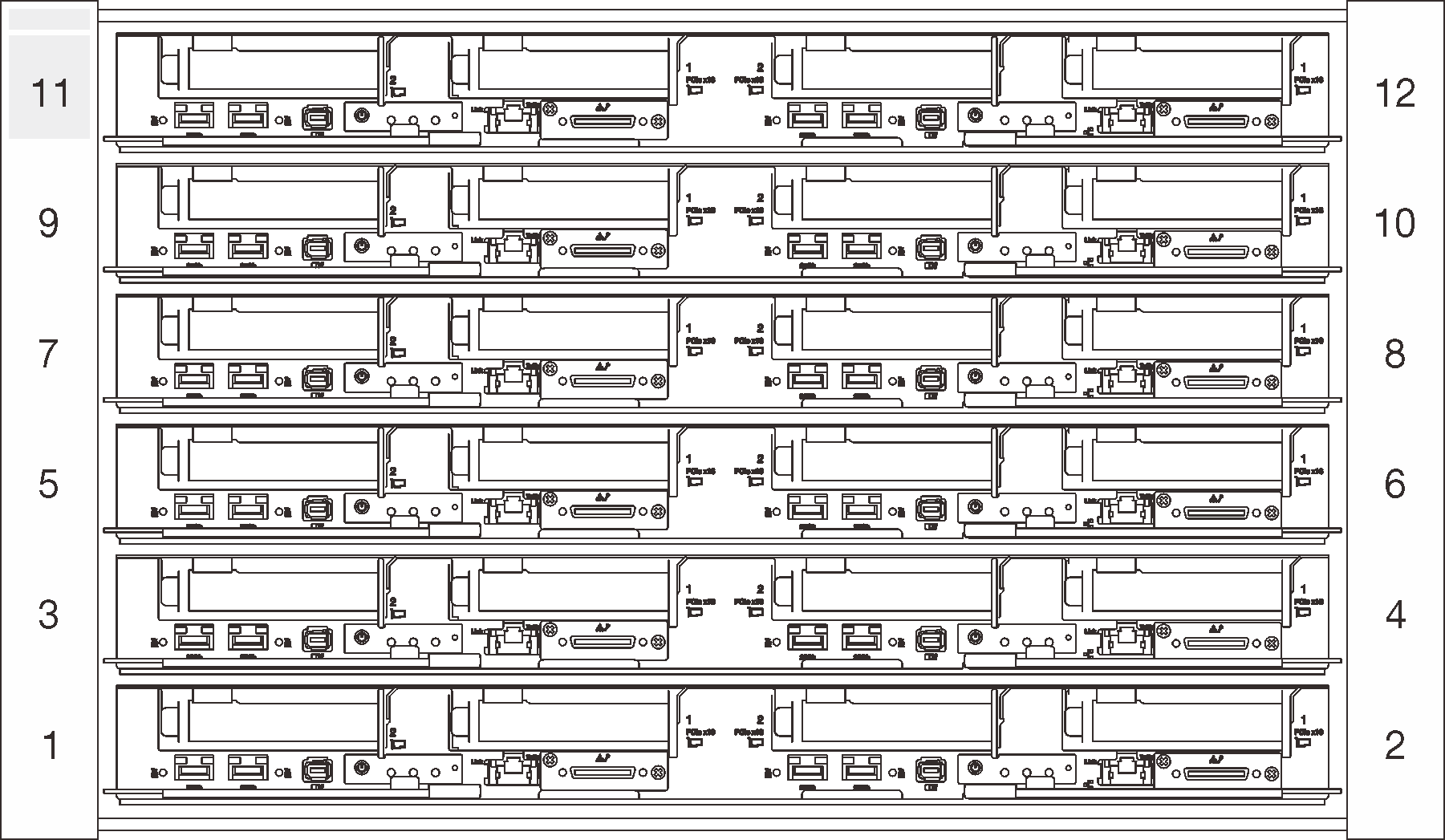
Install the tray starting from enclosure bottom to top (node 1-2 to node 11-12). The tray placement order in the enclosure should be:
Figure 1. Front view of DW612S enclosure installed with six SD650 V3 tray
Refer to Lenovo Press website for individual tray’s maximum inlet water temperature supported and minimum flow rate required. Set CDU temperature setpoint to ensure the lowest maximum supported inlet water is not exceeded. Set CDU flow setpoint to ensure the largest minimum flow rate is delivered to every tray.
If encounter system error in mixing trays configurations, check if the system meets the requirements above. If system error remains, contact Lenovo technician.
