Install the manifold
Use this information to install the manifold.
About this task
CAUTION
The water might cause irritation to the skin and eyes. Avoid direct contact with the lubricant.
S002
CAUTION
The power-control button on the device and the power switch on the power supply do not turn off the electrical current supplied to the device. The device also might have more than one power cord. To remove all electrical current from the device, ensure that all power cords are disconnected from the power source.
S038

CAUTION
Eye protection should be worn for this procedure.
Attention
- Read the following sections to ensure that you work safely.
Ensure proper handling procedures are followed when working with any chemically treated water used in the compute rack cooling system. Ensure that material safety data sheets (MSDS) and safety information are provided by the water chemical treatment supplier and that proper personal protective equipment (PPE) is available as recommended by the water chemical treatment supplier. Protective gloves and eyewear may be recommended as a precaution.
Procedure
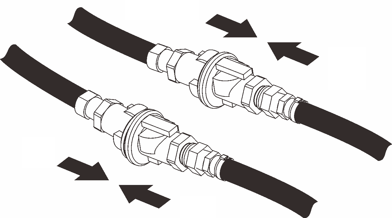
- Install new manifold section into the manifold and connect couplings.Figure 1. Manifold disassemble
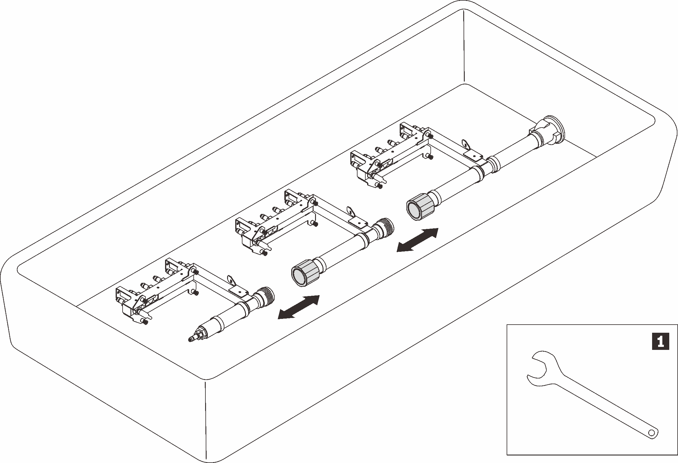
Table 1. Manifold disassemble 1 41mm wrench - Install the manifold.
- ❸ Tighten four screws (using the screwdriver contained in the manifold repair kit) between manifold bracket and enclosure.Figure 2. Manifold installation
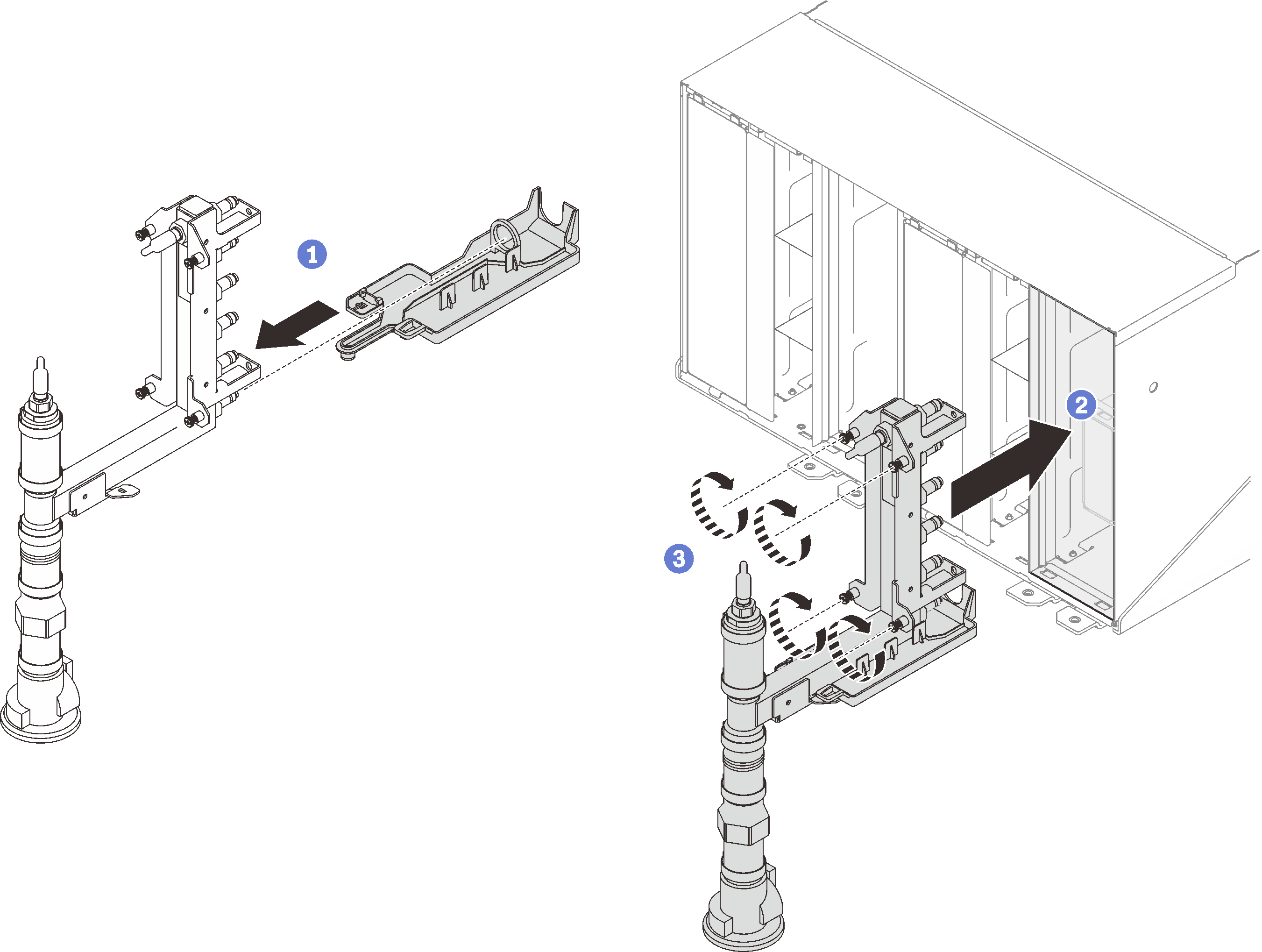 Figure 3. Manifold screw locations
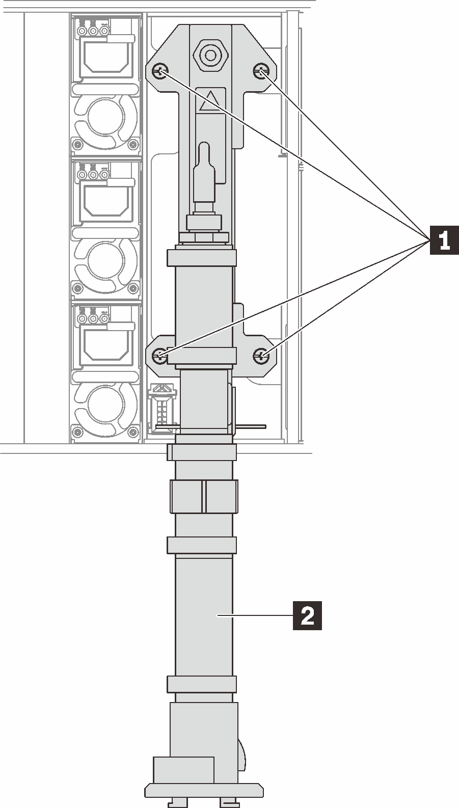
Table 2. Manifold screw locations 1 Screws 2 Manifold
- ❸ Tighten four screws (using the screwdriver contained in the manifold repair kit) between manifold bracket and enclosure.
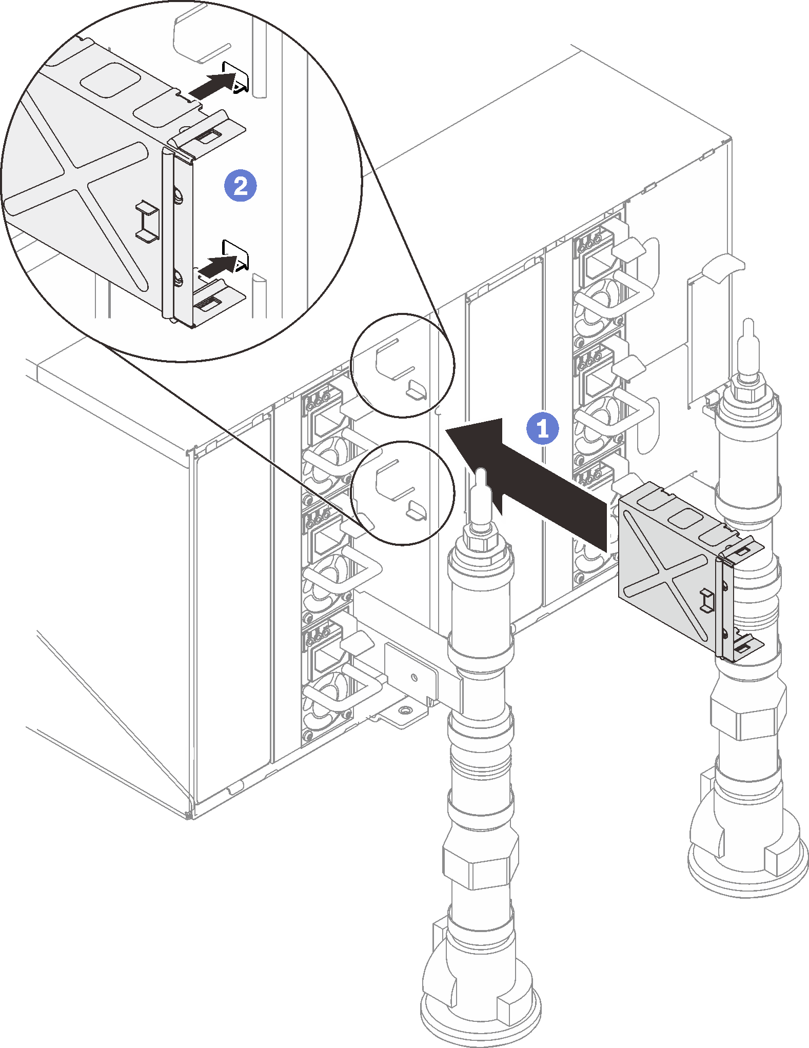
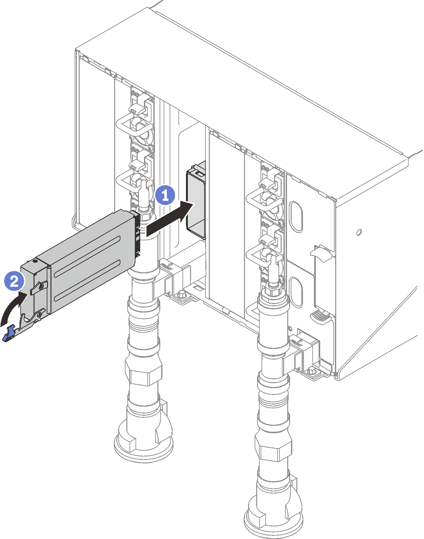
- Reinstall all drip sensor assemblies into enclosure.Figure 4. Drip sensor assembly installation
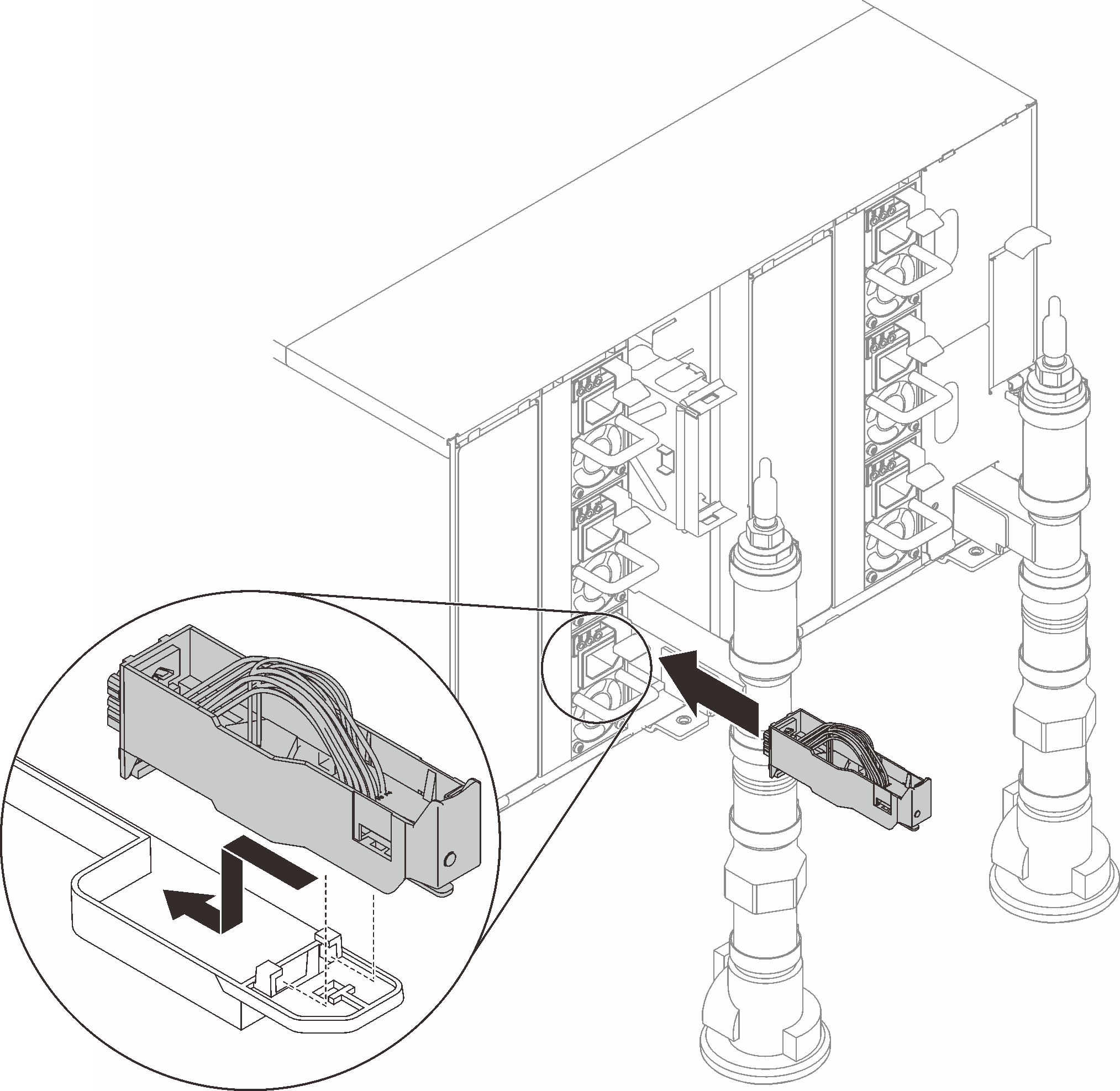 Figure 5. Drip sensor assembly
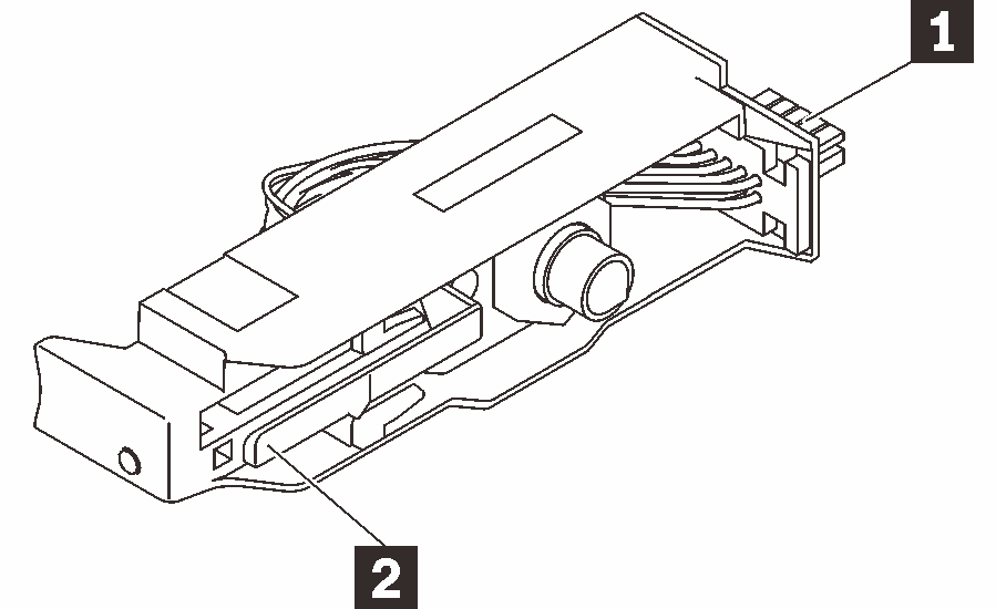
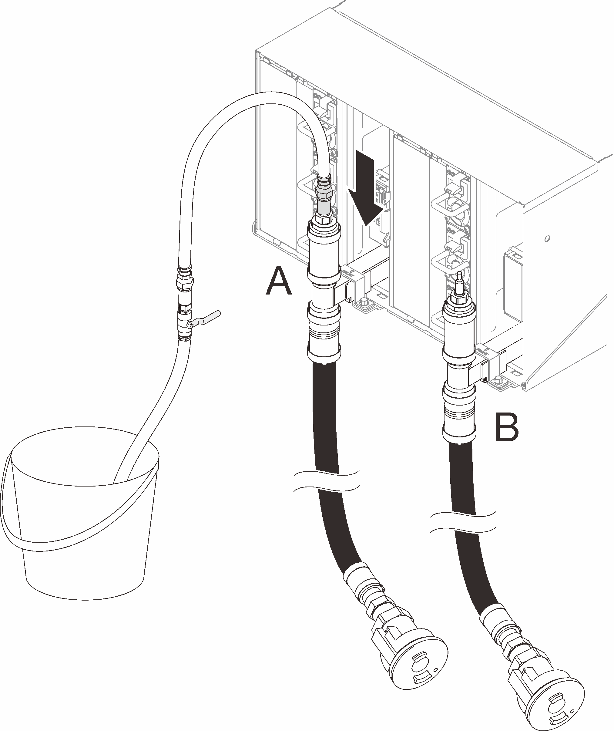
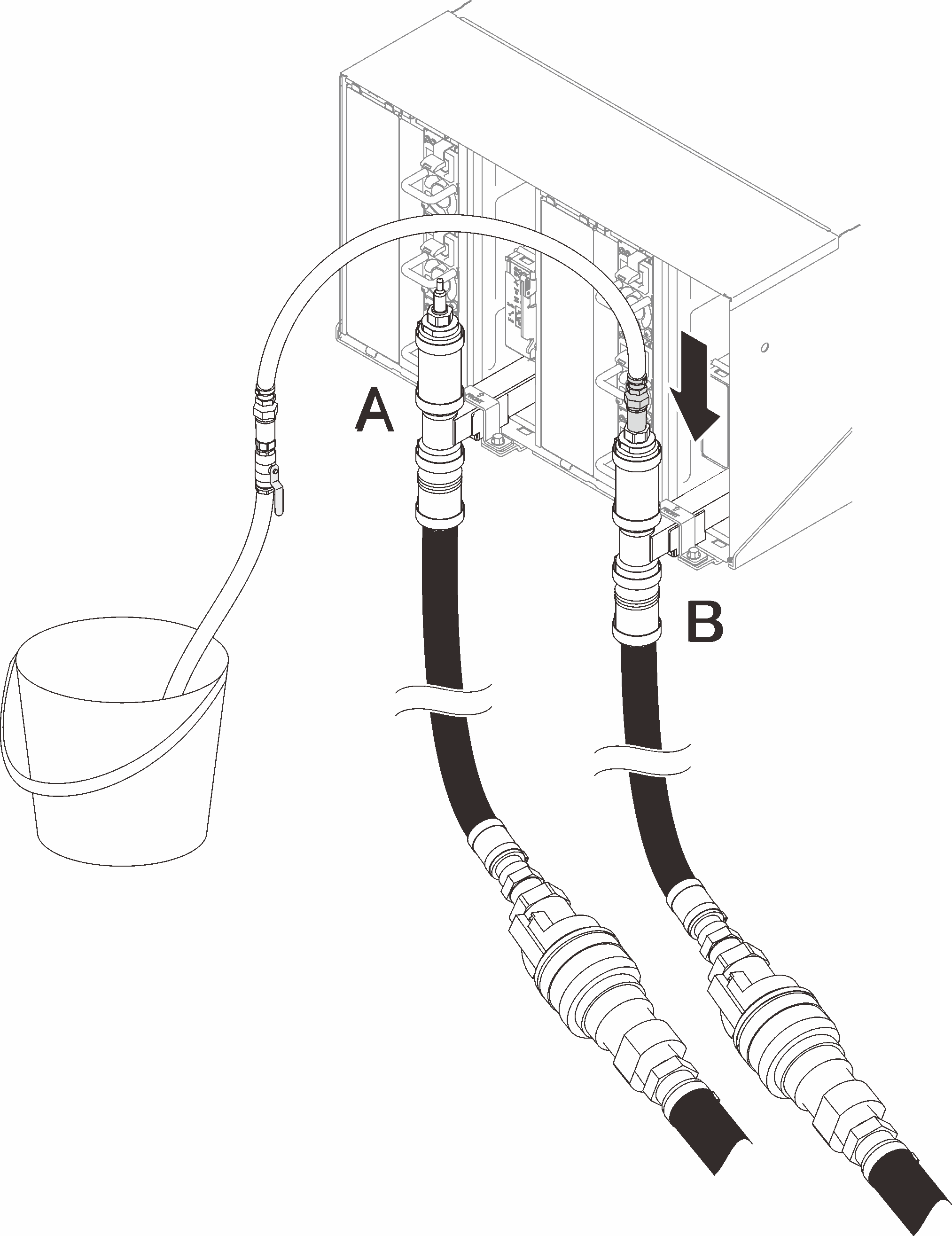
Table 3. Drip sensor assembly 1 Connector 2 Latch - For the manifold water fill/refill process, at the rear of the rack, connect the hose assembly (supplied to customer installation site) to the top quick connect at the top of the rack (location A). Make sure the hose still remains in the bucket with the valve closed (valve handle perpendicular to the hose).NoteThe red plug cover will need to be removed at all positions first in order to plug to the quick connects.Figure 6. Hose assembly to top quick connect connection
- At the front of the rack, connect the facility supply hose to the rack return hose. Partially open the supply hose, about 1/4 of the way.NoteDo not fully open the facility ball valve or you will reduce your ability to control the flow as you fill the rack.Figure 7. Facility supply hose to rack return hose connection
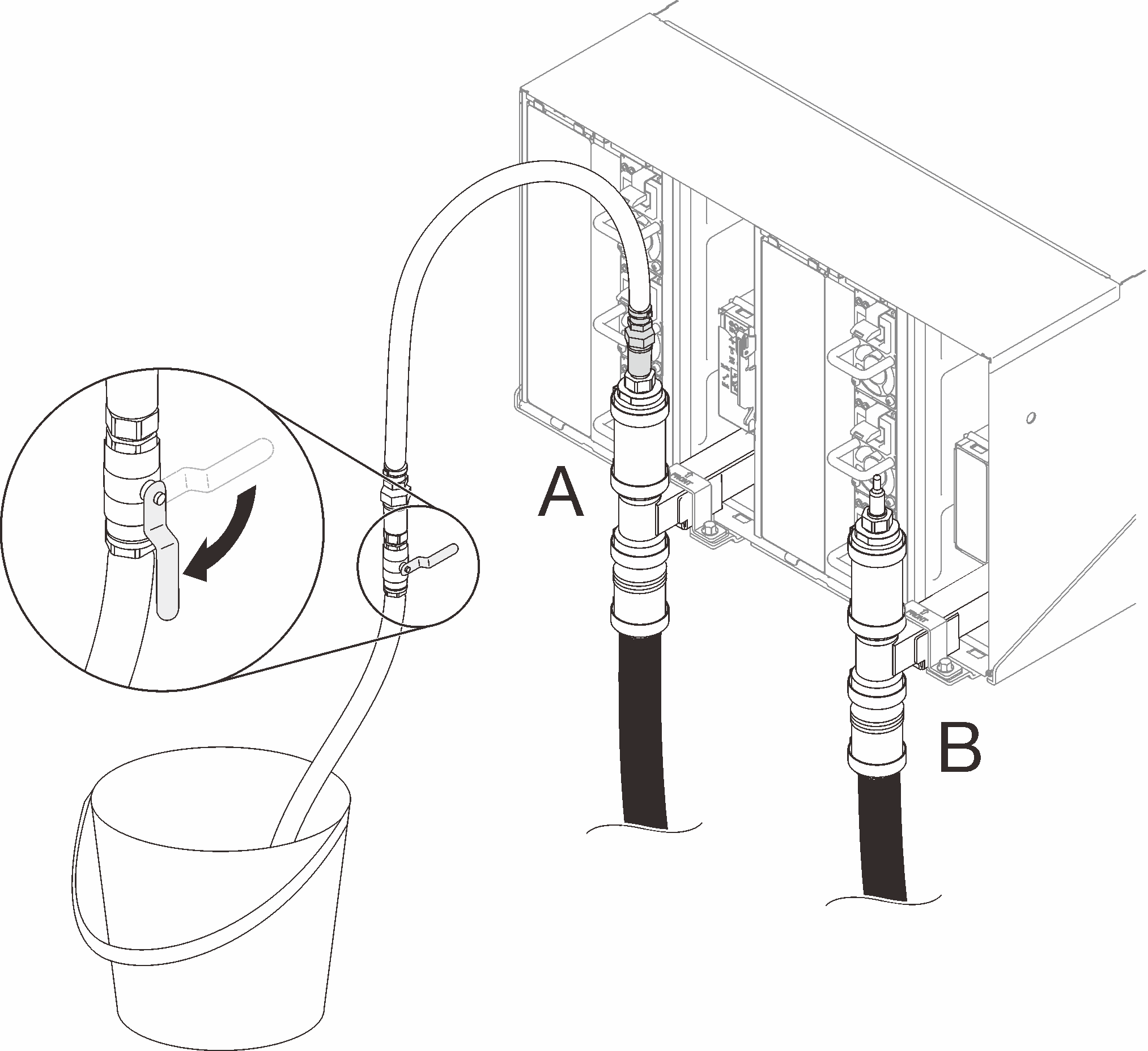
- At the back of the rack, slowly open the valve on the hose part of the way allowing air to flow out of the hose. Allow this to take place until a steady stream of water flows into the bucket or there are minimal bubbles in the sight-glass. It may take approximately one to two minutes for air bubbles to clear the hose.Figure 8. Hose valve opening
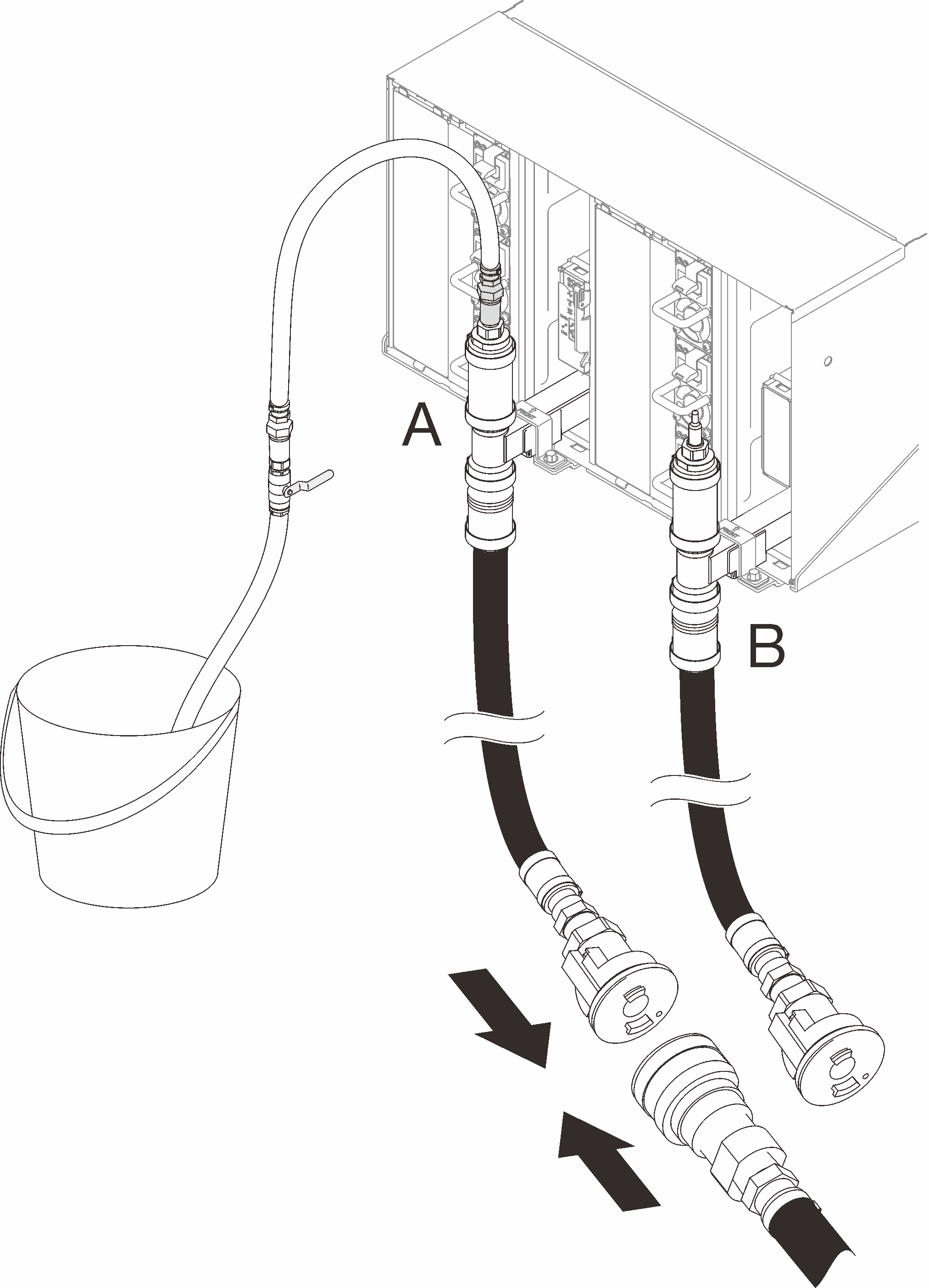
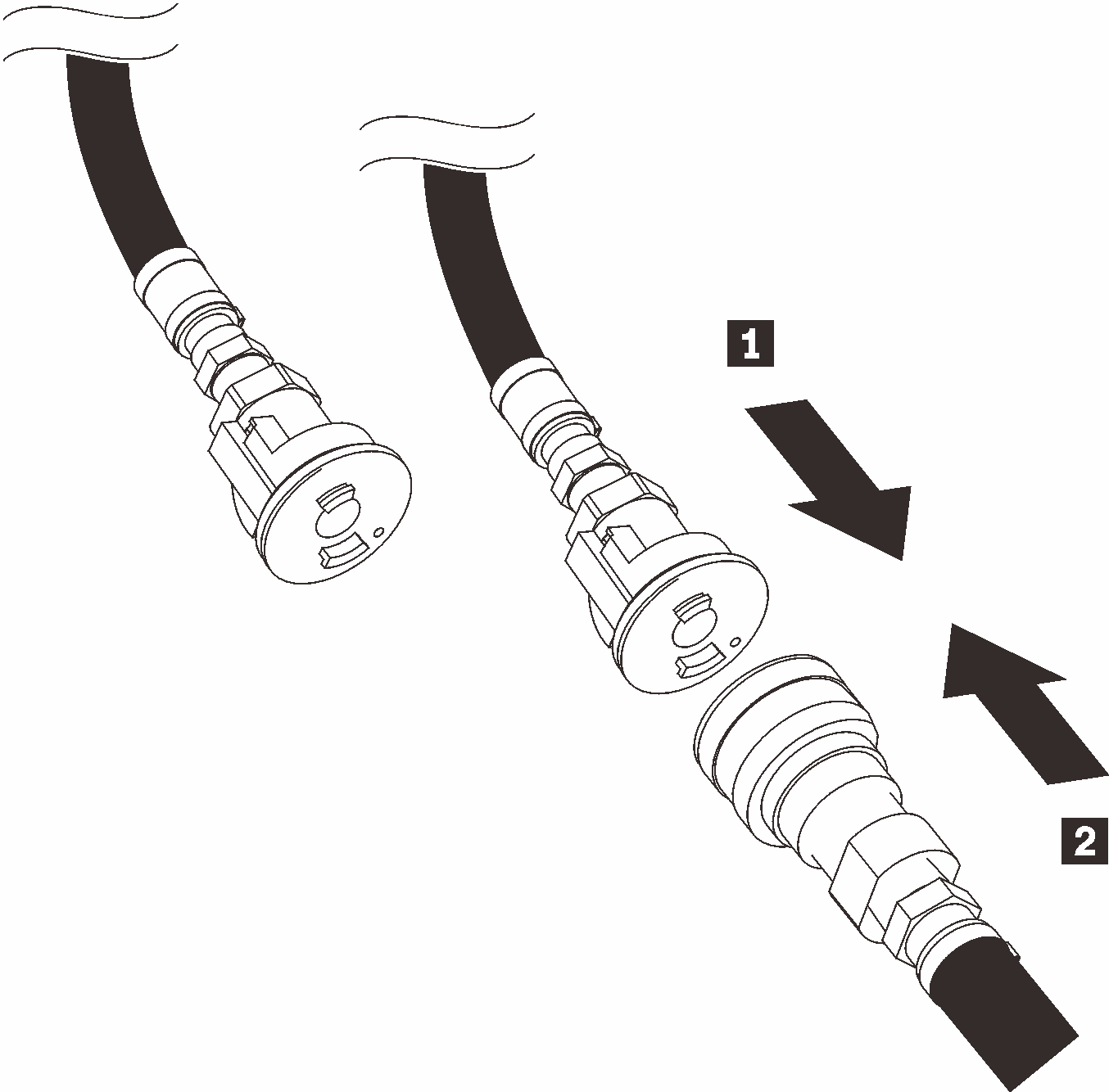
- Close the valve on the hose. Then disconnect the hose assembly from Location A and move to Location B. Slowly open the valve and allow this to stay in place until a steady stream of water flows into the bucket or there are minimal bubbles in the sight-glass. Close the valve on the hose again.Figure 9. Hose assembly movement
- Go back to the front of the rack, disconnect the facility supply hose from the rack return hose and connect the facility supply hose to the rack supply hose.Figure 10. Facility supply hose to the rack supply hose connection
- Again, at the back of the rack, ensure the hose still remains connected to Location B. Open the valve on the hose and leave in place until a steady stream of water flows into the bucket or there are minimal bubbles in the sight-glass.Figure 11. Hose assembly movement
- Close the valve on the hose. Then remove hose assembly from Location B and move to Location A. Open the valve on the hose and allow this to stay in place until a steady stream of water flows into the bucket or there are minimal bubbles in the sight-glass.Figure 12. Hose valve opening
- Close the valve on the hose. Disconnect and move to Location C and open the valve slowly. Leave in place until a steady stream of water flows or minimal bubbles are in the sight-glass. Approximate time 10-15 seconds.Note
- Top position EMC shields on all enclosure positions will need to be removed in order to access the quick connects.
- The red plug covers will need to be removed first in order to access the quick connects.
Figure 13. Hose assembly movement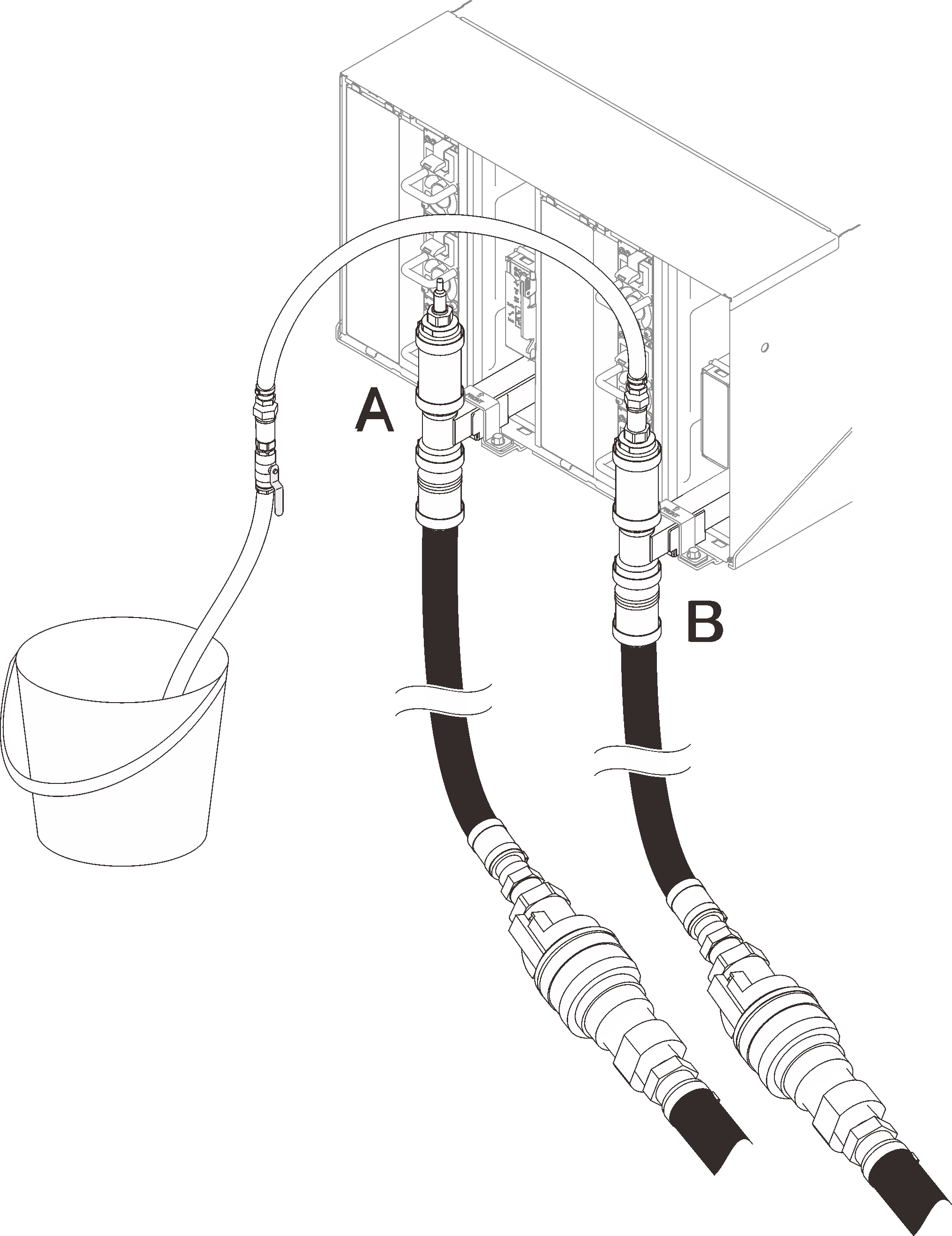
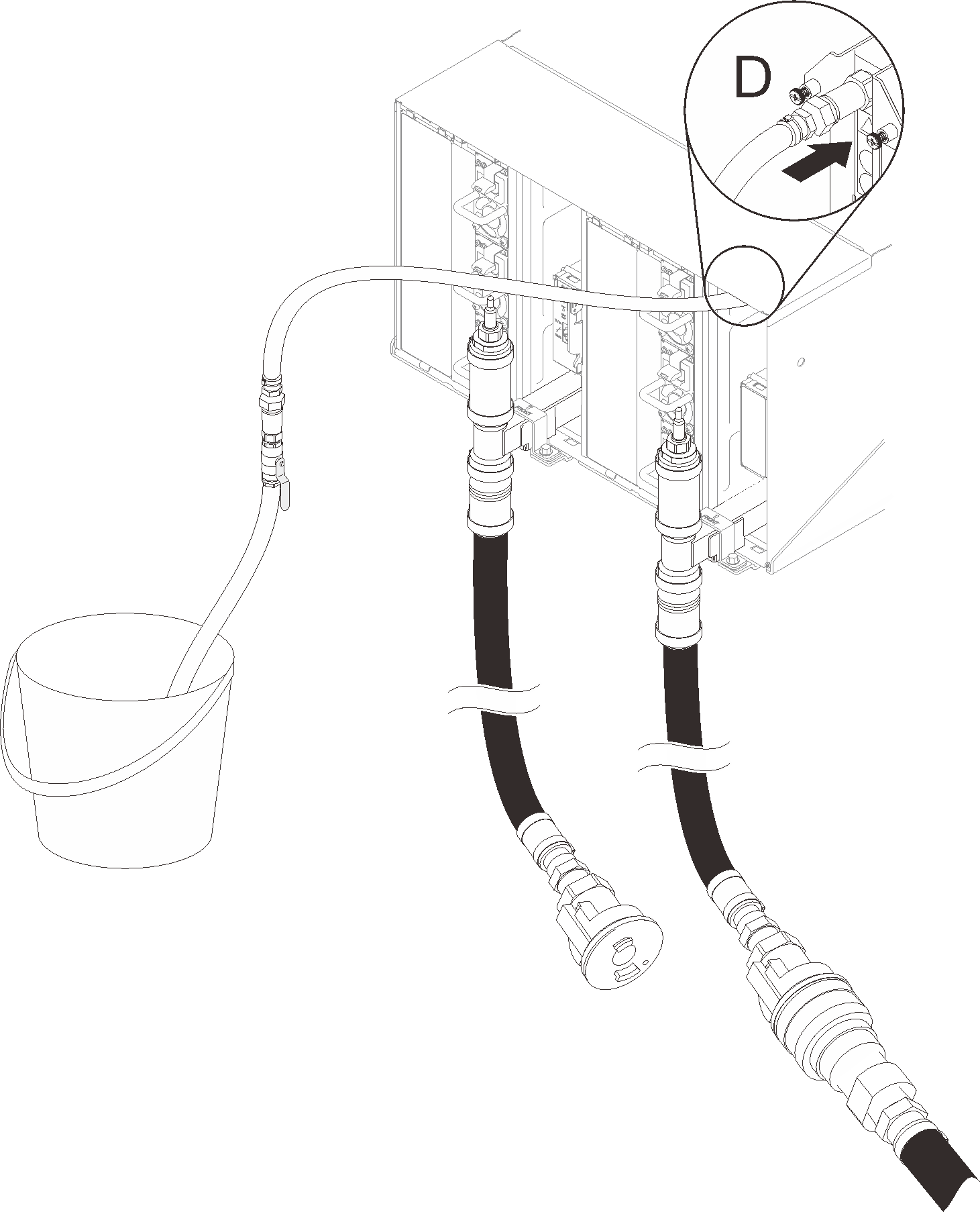
- Close the valve on the hose. Disconnect and move the hose to Location D and repeat the process down the full rack ensuring each enclosure has minimal air bubbles in the sight glass.Figure 14. Hose assembly movement
- Once completed, go back to the front and connect the facility return hose to the rack return hose. Fully open all connections on both the supply and return side. The manifold should be completely filled.Figure 15. Facility return hose to the rack return hose connection
- Install the SMM2 support bracket.Figure 16. SMM2 support bracket installation
- Reinstall the SMM2.Figure 17. SMM2 installation
- Reinstall all EMC shields.Figure 18. EMC shields installation
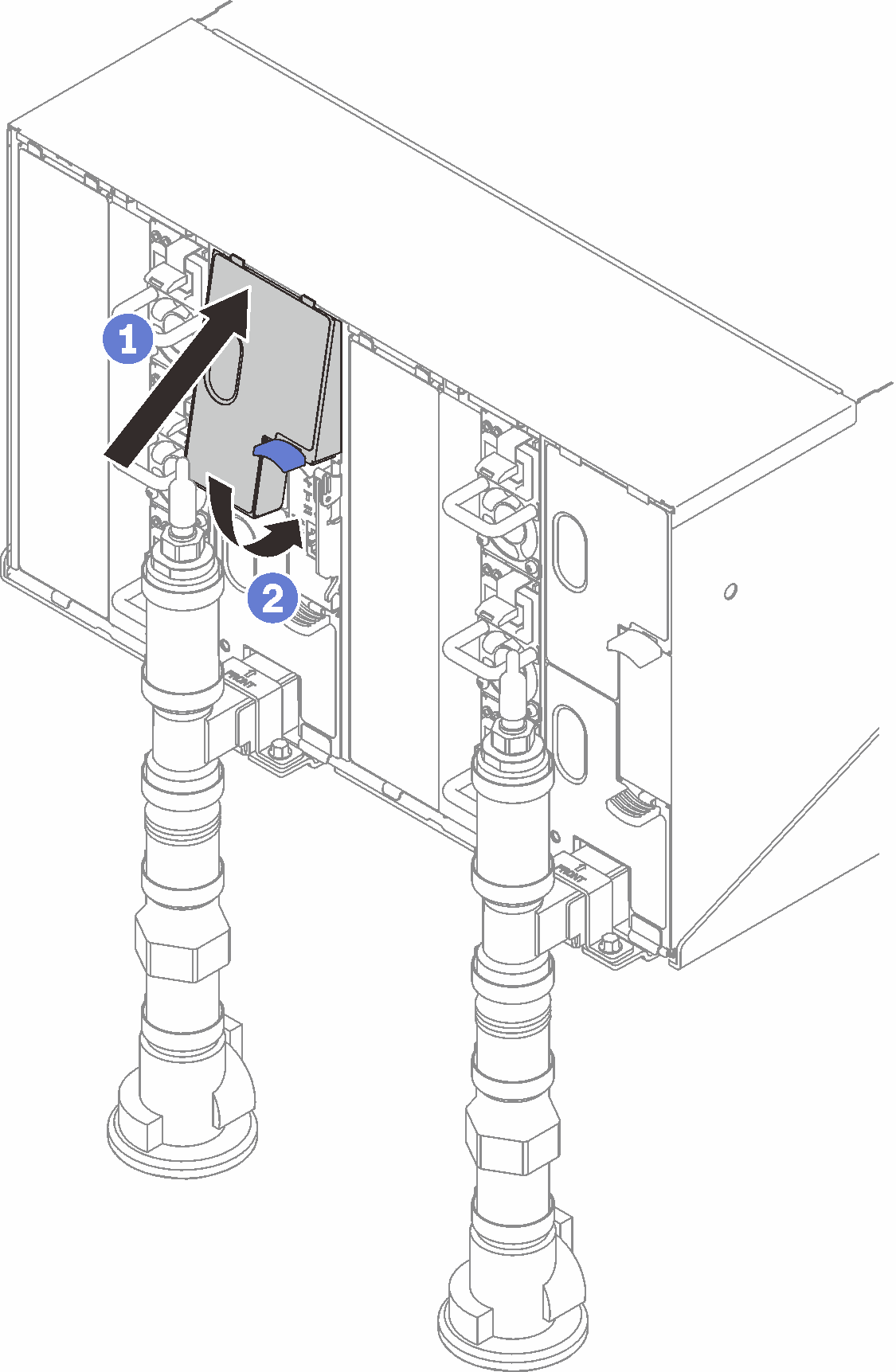 Figure 19. EMC shields installation
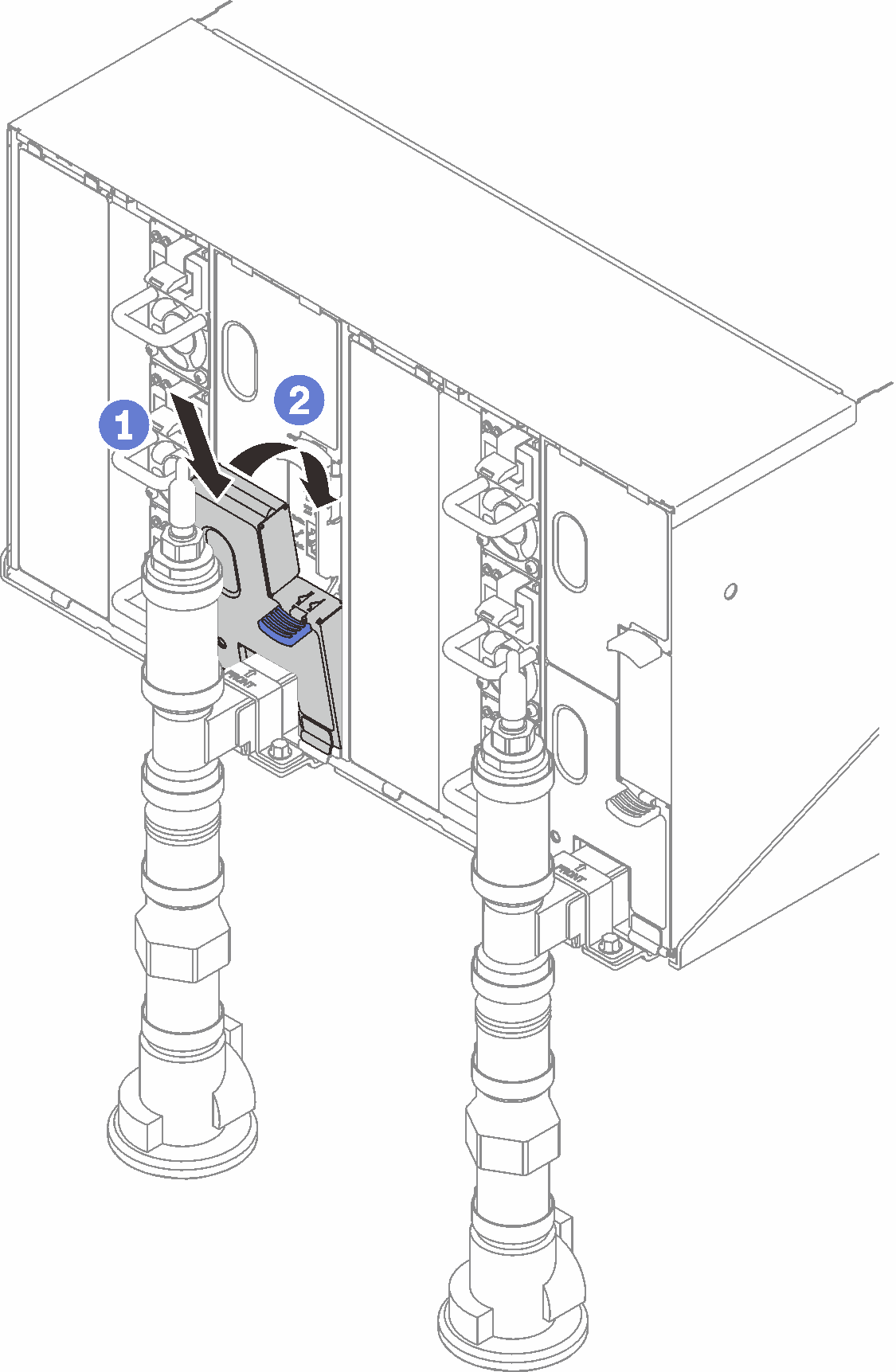 Figure 20. Retention bracket installation
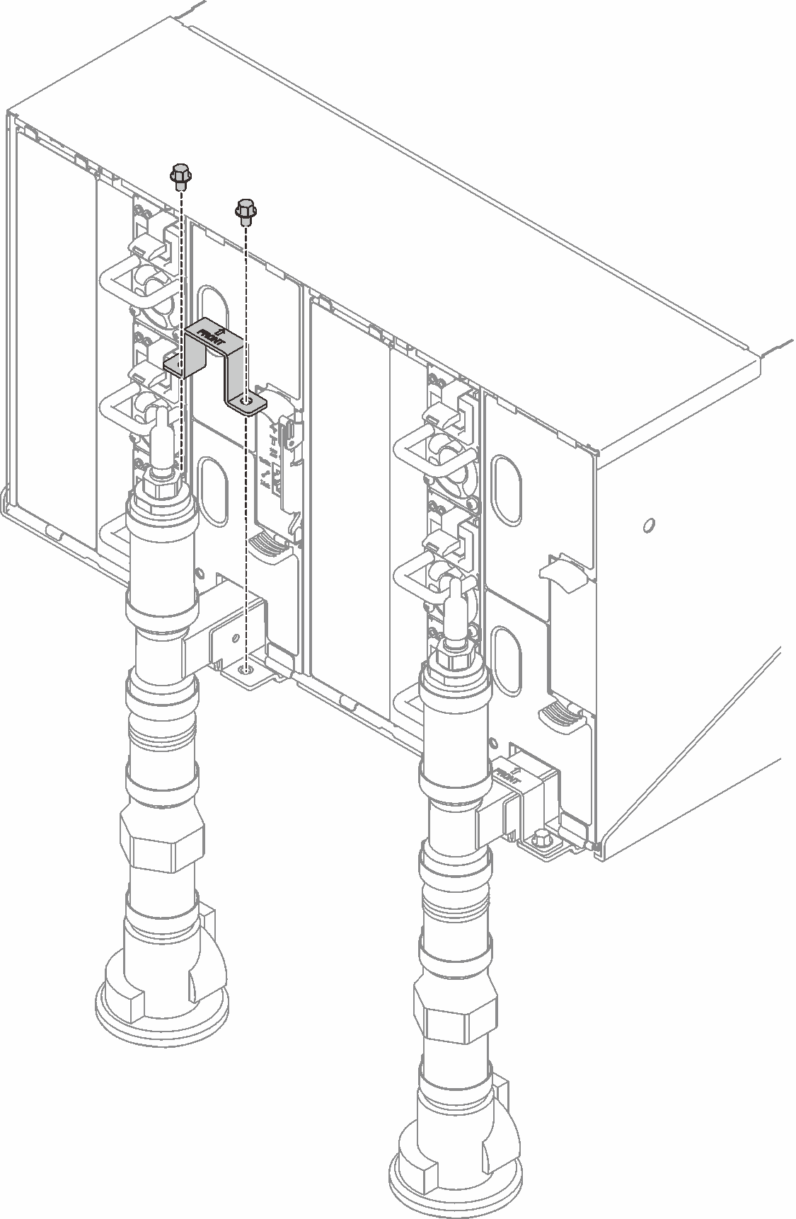
Demo video
Give documentation feedback