Install the retimer board
Use this information to install the retimer board.
Attention
- Read the following sections to ensure that you work safely.
A torque screwdriver is available for request if you do not have one at hand.
Note
Ensure you have “SD650 V2 or SD650-N V2 Neptune® DWC Waterloop Service Kit “ in hand to install components.
Procedure
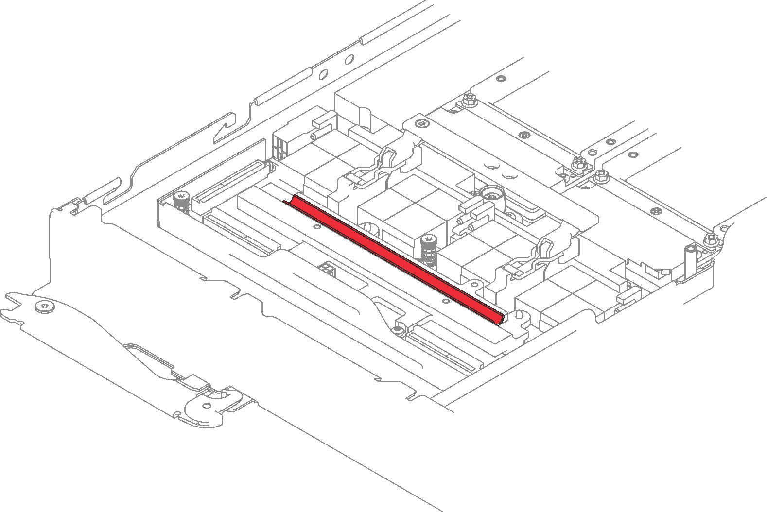
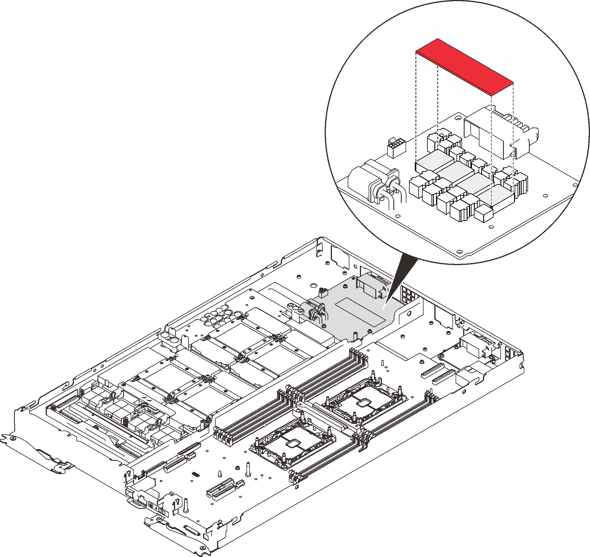
- If the gap pad located on the retimer board is damaged or missing, replace it with the new one.Figure 1. Gap pad on the retimer board
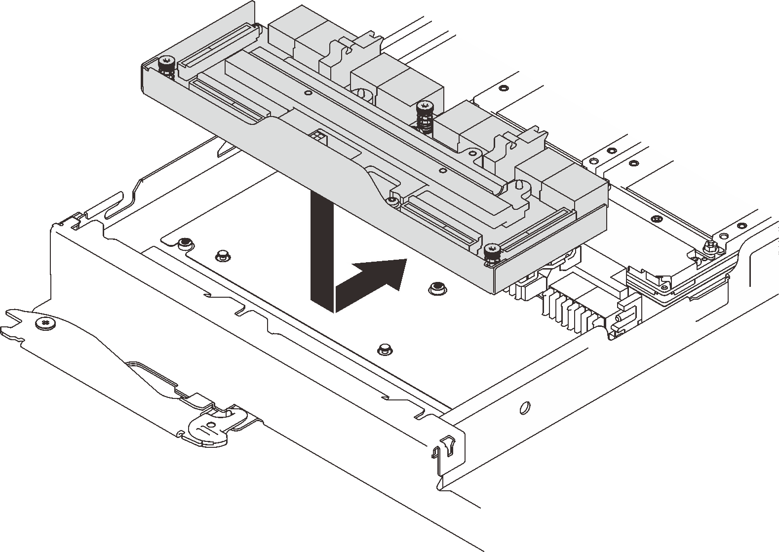
- Place the retimer board into the node and slightly push it to connect the GPU board.Figure 2. Retimer board installation
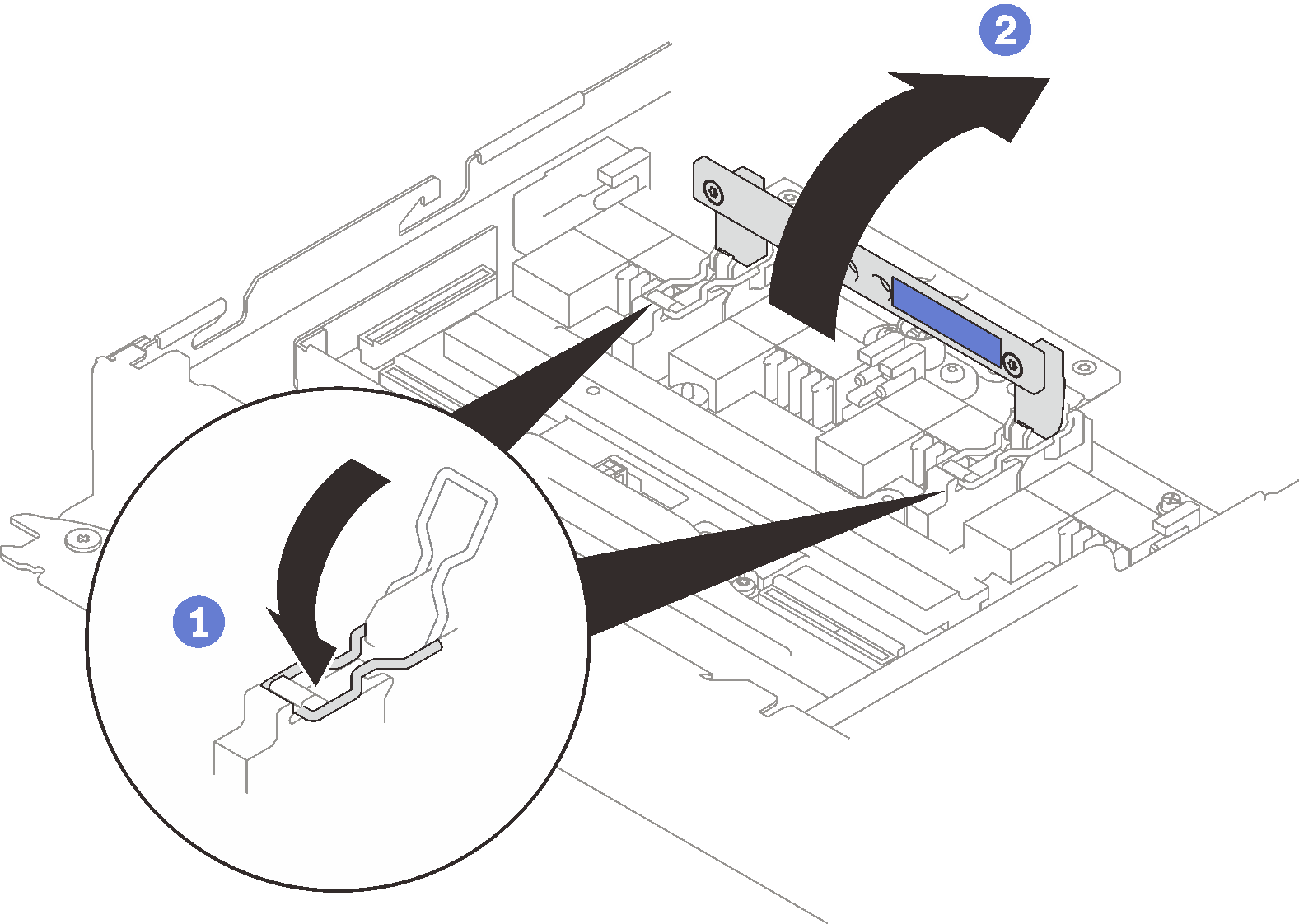
- Place securing clips into the slots and rotate the release handle down.Figure 3. Rotating the handle
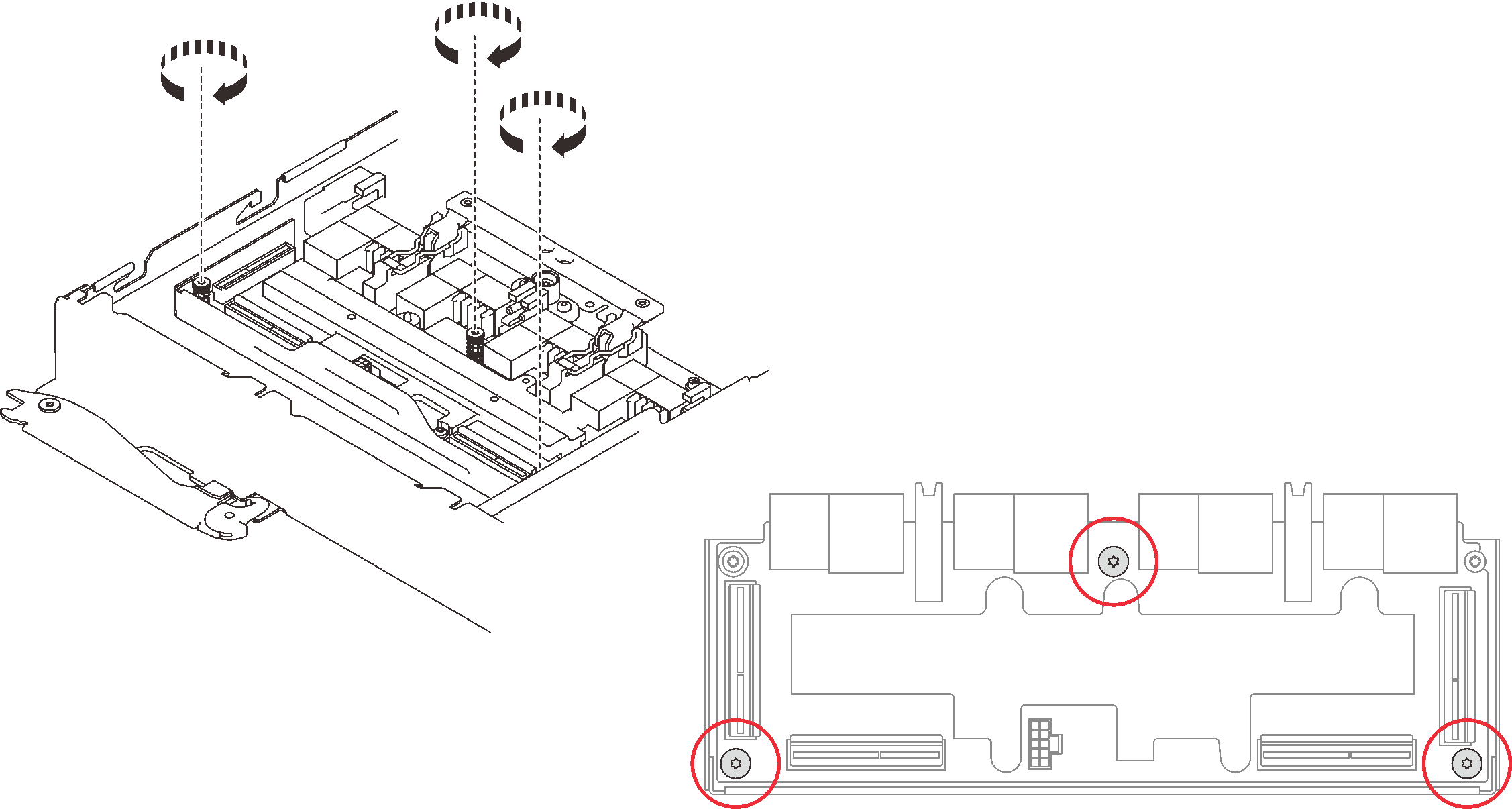
- Install the three screws to secure the retimer board.Figure 4. Retimer board installation
- Apply the new thermal grease on GPUs.
- If there is any old thermal grease on four GPUs and the cold plates, gently clean the top of the four GPUs and the cold plates using an alcohol cleaning pad.
- If you have cleaned the top of the GPUs with an alcohol cleaning pad, make sure to apply the new thermal grease after the alcohol has fully evaporated.
- Apply gray thermal grease to the top of the four GPUs with a syringe by forming four dots spaced as shown below, with each dot consisting of about 0.5 gram (about 0.225 ml) of gray thermal grease. Each syringe contains 1 gram of thermal grease, sufficient for two dots of thermal grease.
Figure 5. Thermal grease application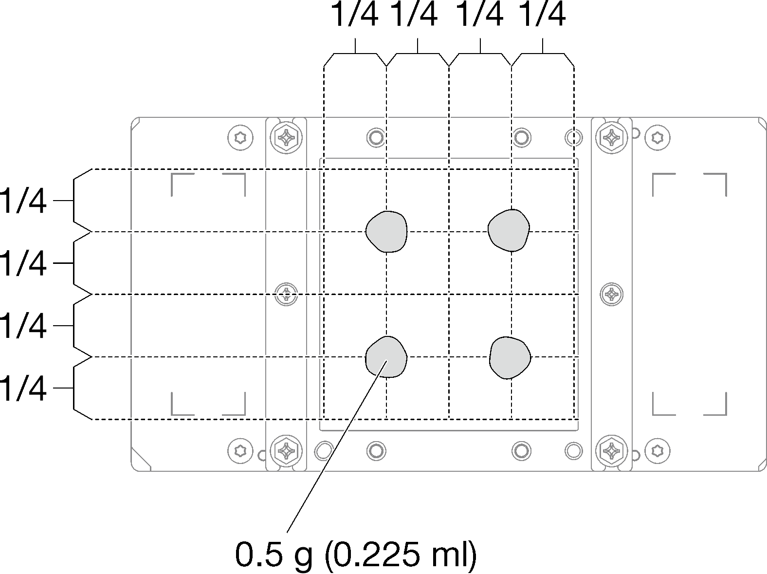
- Replace the existing putty pad with the new one.Figure 6. Putty pad
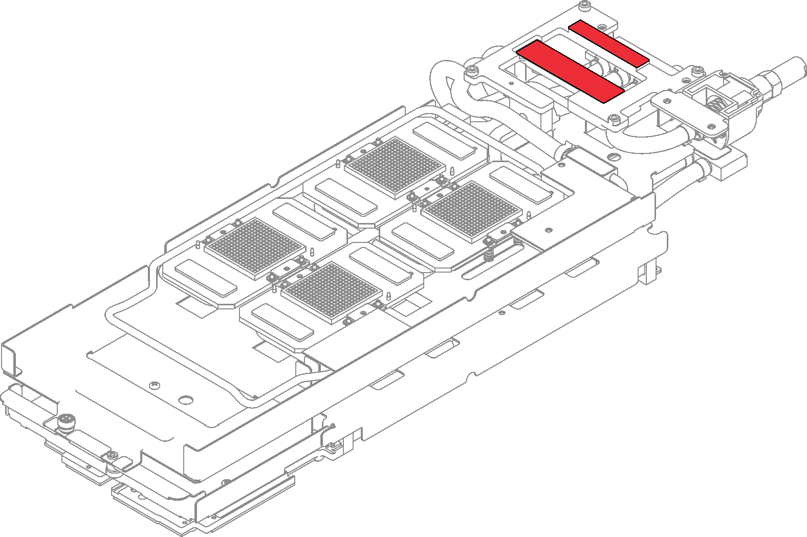
- Check the gap pads on the water loop, if any of them are damaged or missing, replace them with the new ones.Figure 7. Gap pads on the water loop
- Reinstall the water loop.
- ❸ Carefully align the water loop with eight guide pins on four GPU cold plates; then, gently put the water loop down and ensure it is firmly seated on the GPU board.Figure 8. Water loop installation

- ❸ Carefully align the water loop with eight guide pins on four GPU cold plates; then, gently put the water loop down and ensure it is firmly seated on the GPU board.
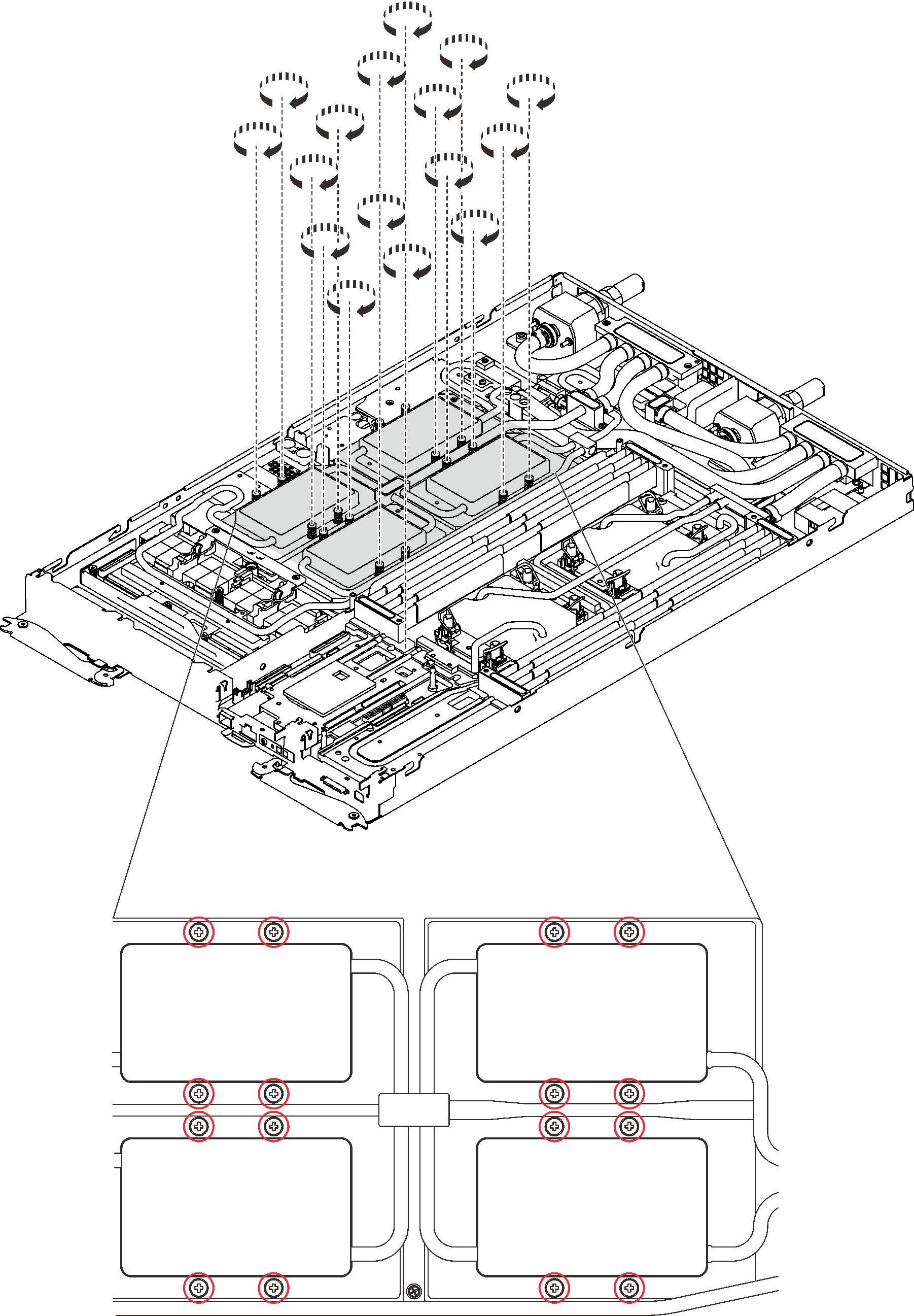
- Loosen all water loop carrier screws (15x Phillips #2 screws).Figure 9. Loosening water loop carrier screws
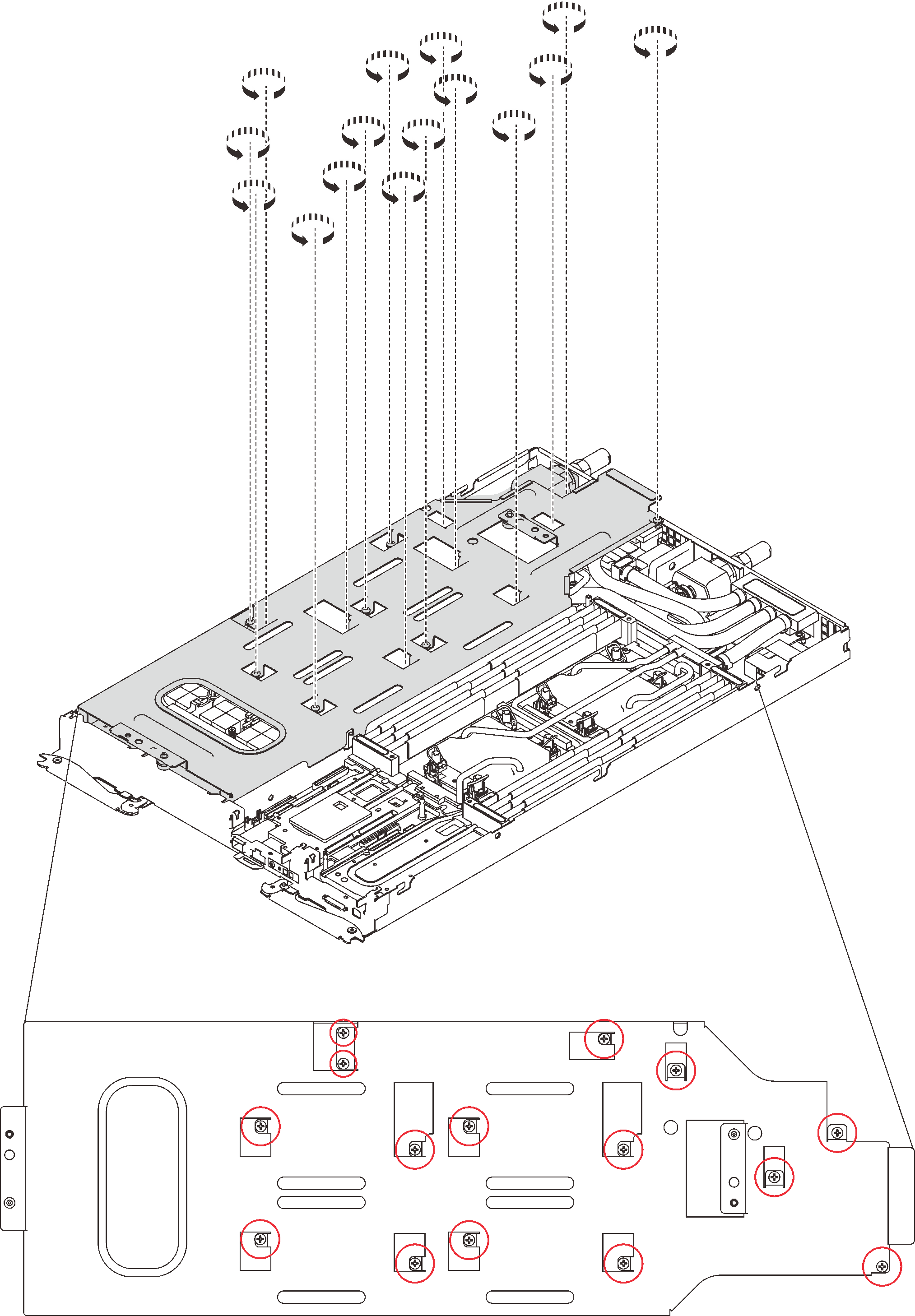
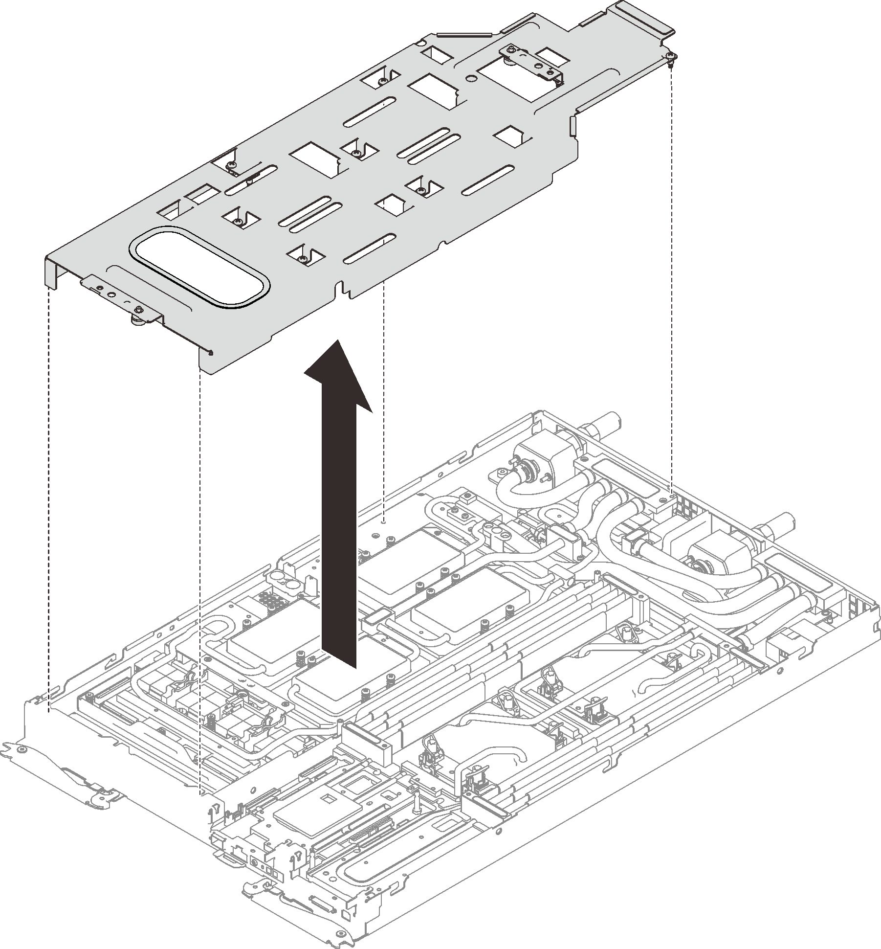
- Carefully lift the water loop carrier up and away from the water loop.Figure 10. Water loop carrier removal
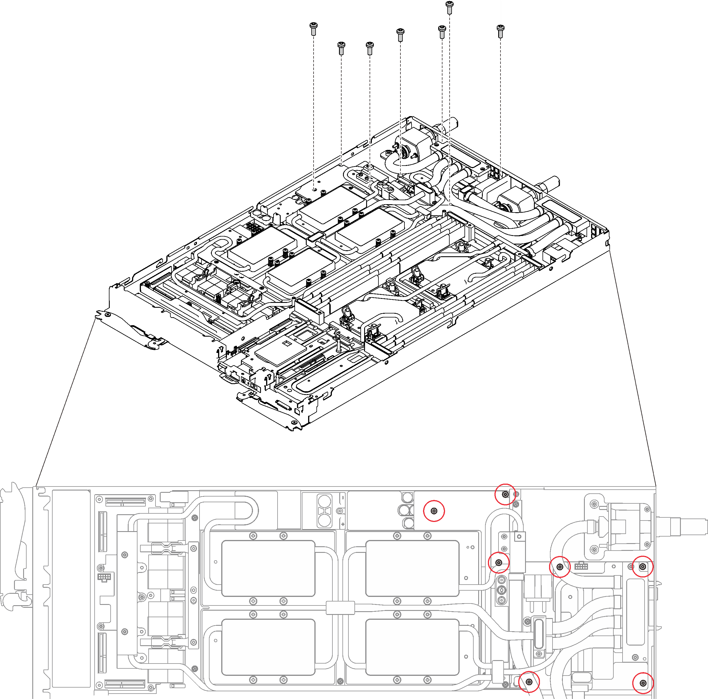
- Reinstall water loop screws (7x Torx T10 screws) with a torque screwdriver sets to the proper torque.NoteFor reference, the torque required for the screws to be fully tightened/removed is 0.5-0.6 newton-meters, 4.5-5.5 inch-pounds.Figure 11. Water loop screws installation
- Reinstall GPU cold plate screws (4x Phillips #1 screws per GPU cold plate, total of 16x Phillips #1 screws) with a torque screwdriver set to the proper torque. For reference, the torque required for the screws to be fully tightened/removed is 0.34-046 newton-meters, 3-4 inch-pounds.Figure 12. GPU cold plate screws installation
 Push down the GPU cold plate with your palm to reduce the gap between the GPU cold plate and the GPU.
 Press the torque screwdriver against the screw so that the screw is engaged with the GPU.
 Follow the screw sequence specified on the GPU cold plate label, and fasten each screw for 720 degrees with a torque screwdriver set to the proper torque.NoteFor reference, the torque required for the screws to be fully tightened/removed is 0.46–0.34 newton-meters, 4–3 inch-pounds.
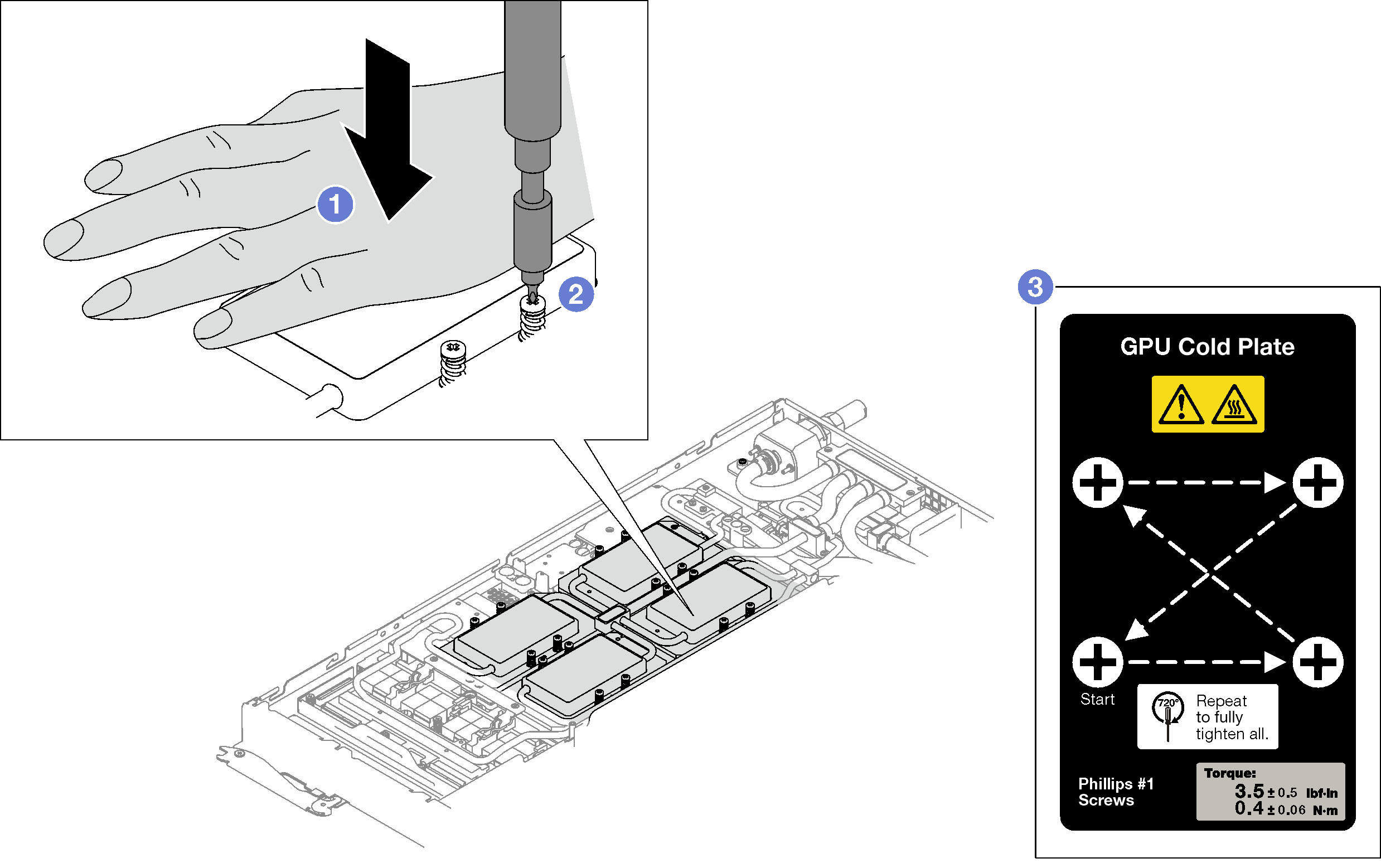
 Make sure that the GPU cold plate is lowered into the node and its surface is flat without tilting. If the GPU cold plate is tilted, unfasten the screws, and repeat Step 1 to Step 3.
 Repeat Step 3 until the screws are fully tightened.
 Make sure the height of each screw is 12.5±0.3 millimeter (0.49±0.01 inch) and is fully compressed. If not, repeat the GPU cold plate installation steps.
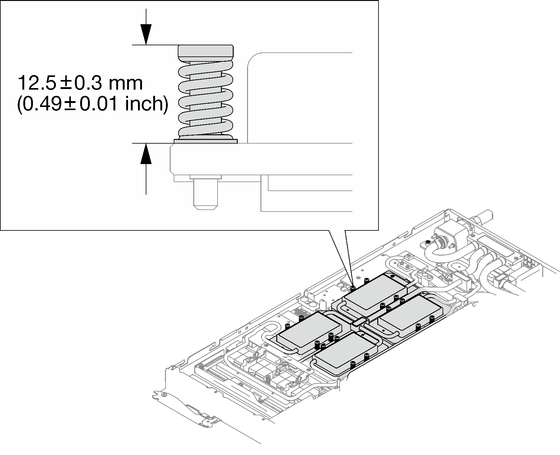 NoteInspect the screws to make sure they are fully compressed.
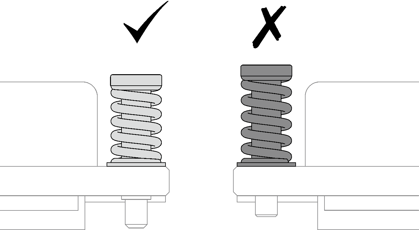
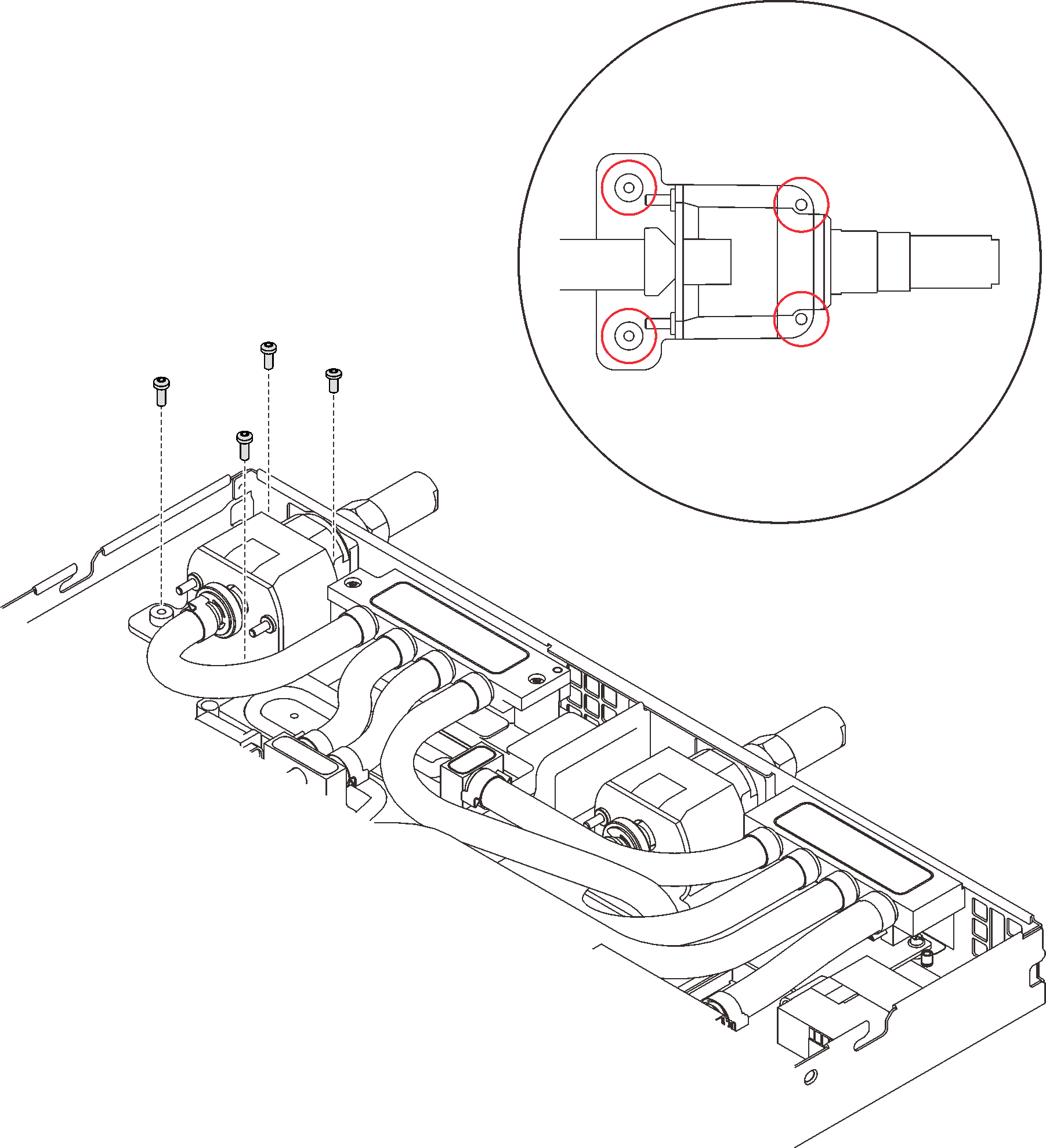
- Reinstall the four Torx T10 screws (per node) to secure the quick connect.Figure 13. Screws installation
- Reinstall the clamp plate or the drive depending on your configuration.
Clamp plate installation: Install the two screws to secure the clamp plate.
Figure 14. Clamp plate installation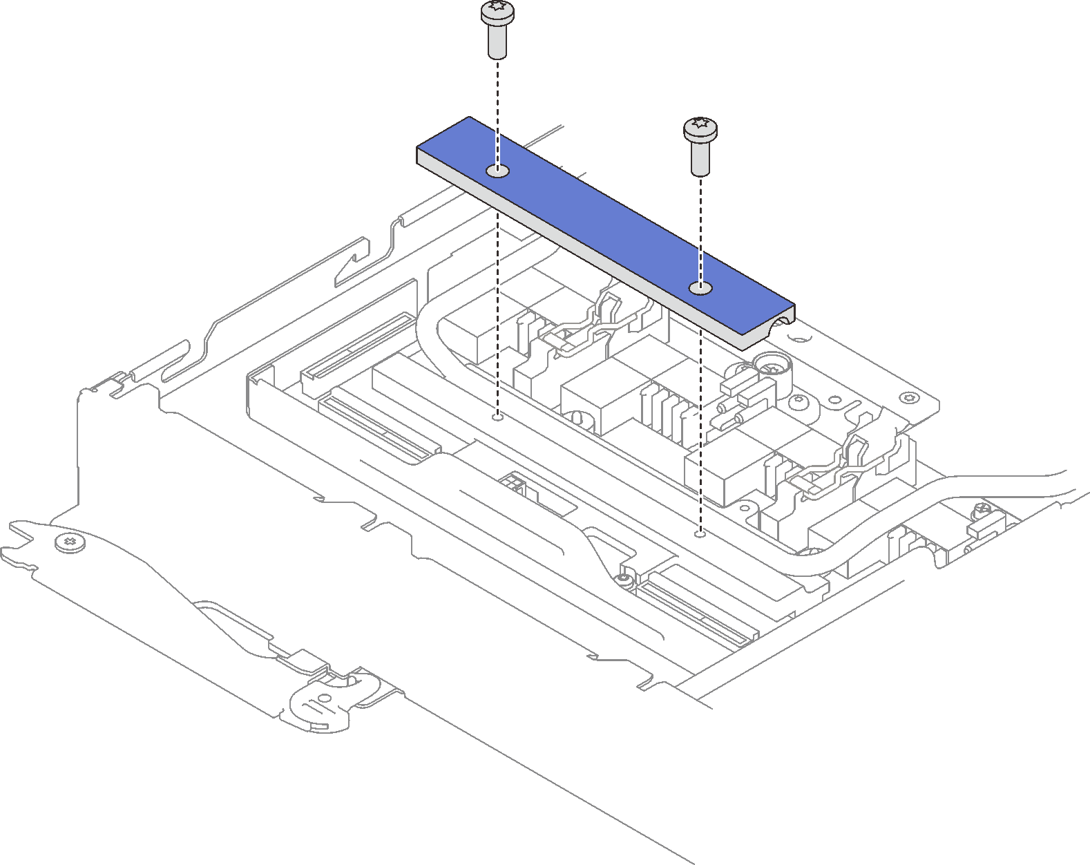
Drive installation: see Install the drive in the GPU node.
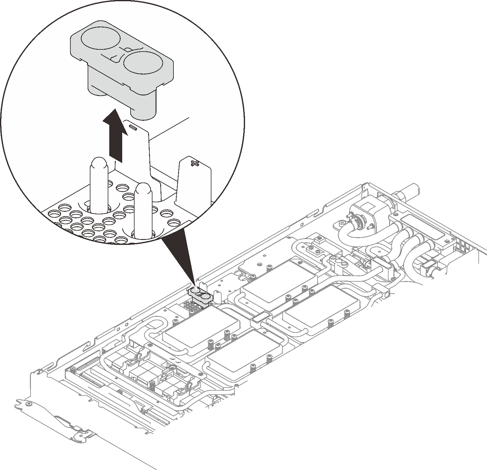
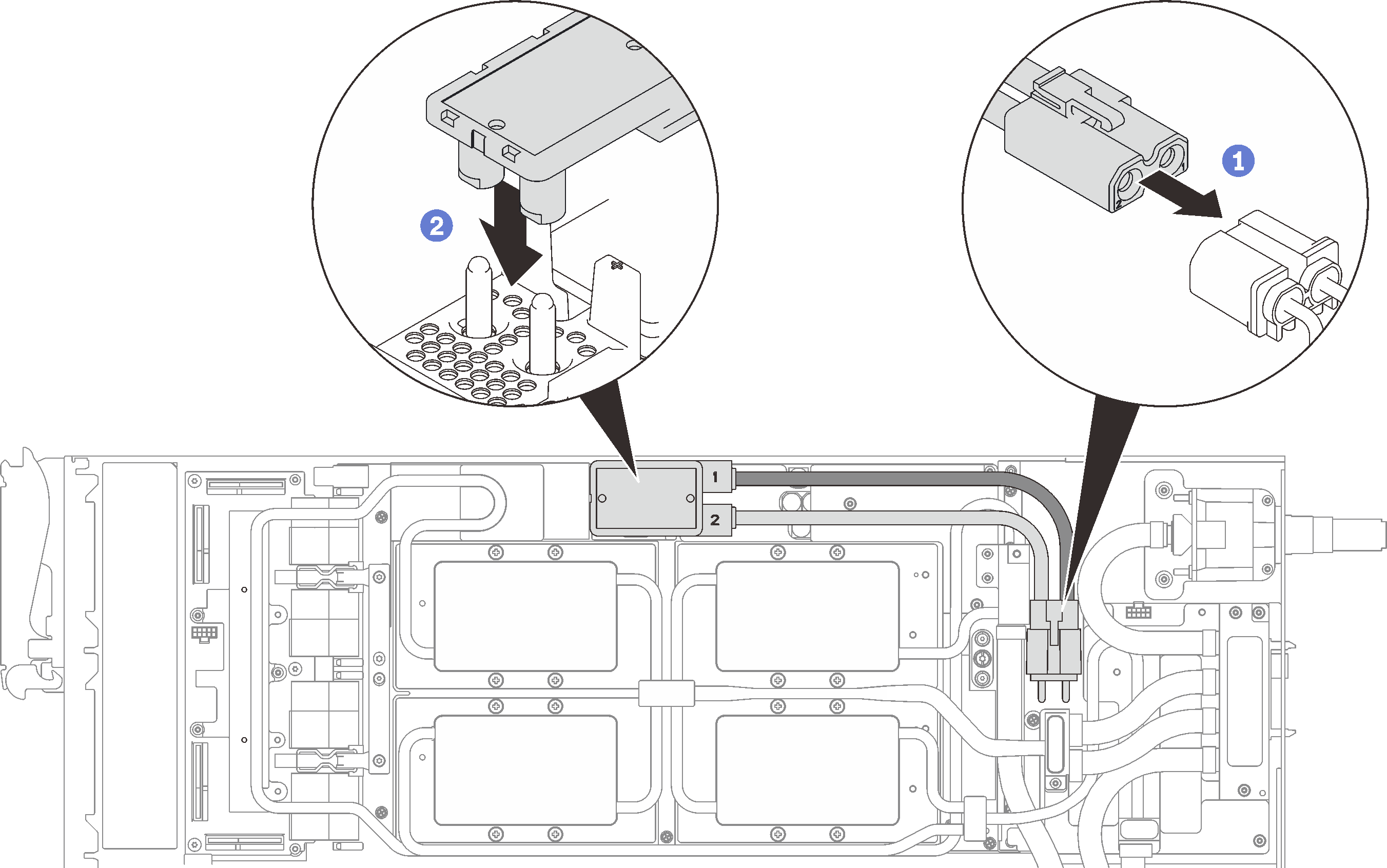
- Remove the connector cover if necessary.Figure 15. Connector cover removal
- Connect GPU power cable.Figure 16. GPU power cable installation
After you finish
Reinstall the front and the rear cross braces (14x Phillips #1 screws).
Figure 17. Cross brace installation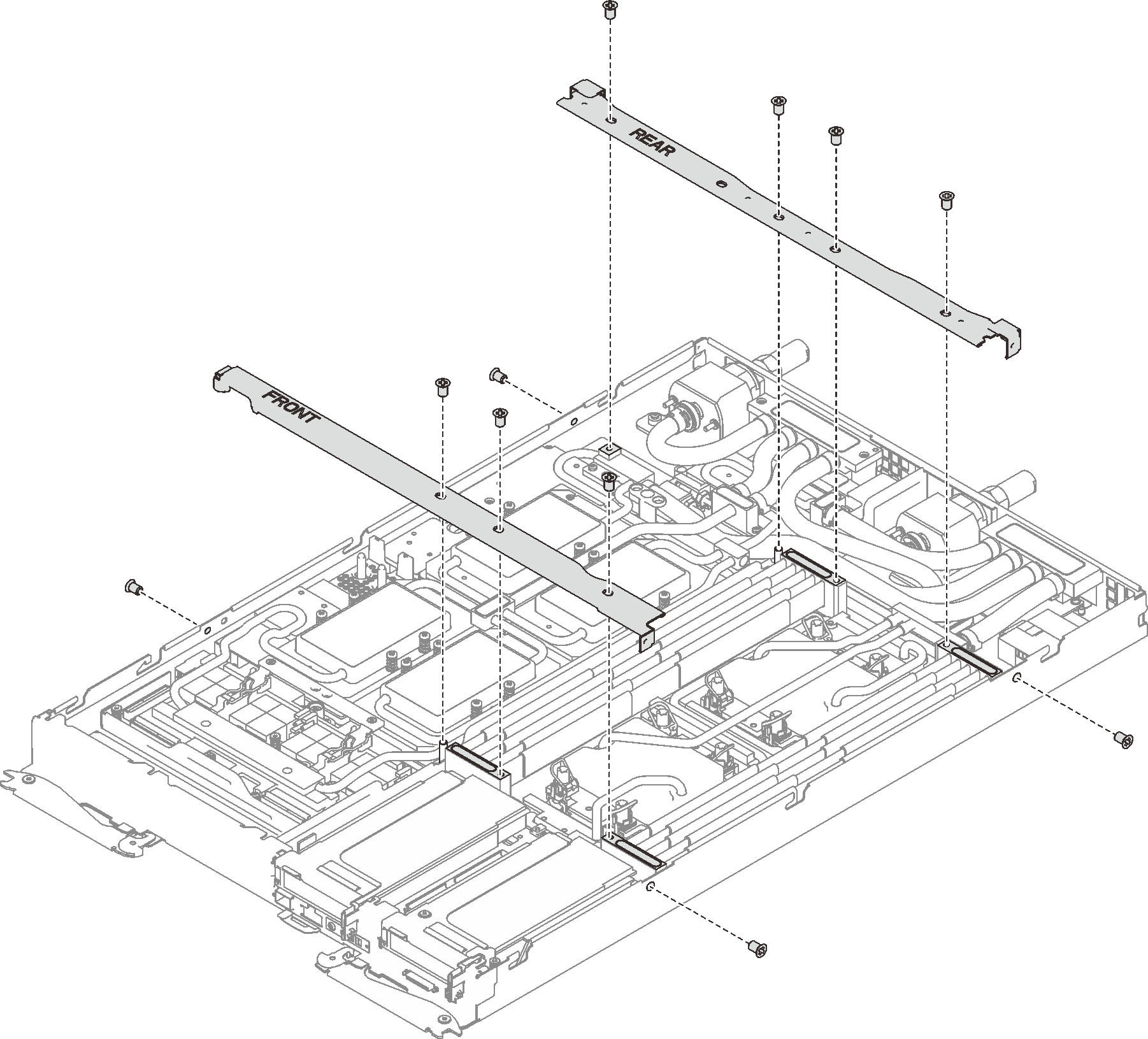
Reinstall the tray cover (see Install the tray cover).
Reinstall the tray (see Install a DWC tray in the enclosure).
NoteFor safety, use the lift tool to install the tray into the rack.- Connect all required external cables to the enclosure.NoteUse extra forces to connect QSFP cables to the enclosure if Mellanox ConnectX-6 adapters are installed.
Check the power LED on each node to make sure it changes from fast blink to slow blink to indicate all nodes are ready to be powered on.
Demo video
Give documentation feedback