Fan power control (FPC) module
The following illustration shows the connectors and LEDs on the FPC module.
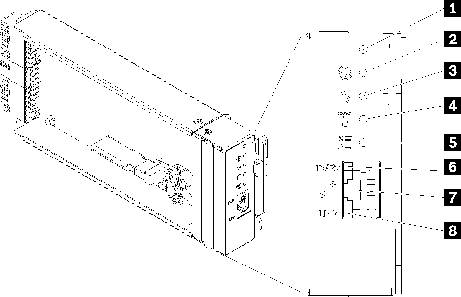
| 1 Reset button hole | 5 Check log LED (yellow) |
| 2 Power LED (green) | 6 Ethernet port activity (RJ-45) LED (green) |
| 3 Activity LED (green) | 7 Dedicated Ethernet port for FPC management access |
| 4 Identification LED (blue) | 8 Ethernet port link (RJ-45) LED (green) |
1 Reset button: Press the button for 1 to 4 seconds, FPC reboots. Press over 4 seconds, FPC reboots and loads to the default settings.
2 Power-on LED: When this LED is lit (green), it indicates that the FPC has power.
3 Activity LED: When this LED is lit (green), it indicates that the FPC is actively controlling the enclosure.
4 Identification LED: When this LED is lit (blue), it indicates the enclosure location in a rack.
5 Check log LED: When this LED is lit (yellow), it indicates that a system error has occurred. Check the FPC event log for additional information.
6 Ethernet port activity (RJ-45) LED: When this LED is flashing (green), it indicates that there is activity through the remote management and console (Ethernet) port over the management network.
7 Dedicated Ethernet port for FPC management access: Use this connector to access FPC management.
8 Ethernet port link (RJ-45) LED: When this LED is lit (green), it indicates that there is an active connection through the remote management and console (Ethernet) port to the management network.