Remove the enclosure midplane
Use this information to remove the enclosure midplane.
Before you remove the enclosure midplane:
Read the Installation Guidelines to ensure that you work safely.
Three people are needed to complete this task.
- Record the machine type model, the enclosure serial number, and retrieve the existing universally unique identifier (UUID) information from the enclosure midplane that you are removing. The procedure for obtaining this data might require different steps depending on the functional state of the enclosure.
- Enclosure is operating:
- Log onto the Lenovo XClarity Controller and access the command-line interface (CLI). You can access the XCC CLI through a direct serial or Ethernet connection to the XCC, or through a Secure Shell (SSH) connection to the XCC. You must authenticate with the XCC before issuing commands.
- Query for the machine type model, enclosure serial number, and the UUID values by using the CLI info command. Record this information before you proceed.
- Enclosure is not operating:
- Obtain the enclosure serial number and the machine type model from one of the enclosure labels.
- Record the enclosure serial number, the machine type model, and the UUID before you proceed.
- Enclosure is operating:
- Shut down the operating system and turn off any compute nodes in the enclosure. See the documentation that comes with the compute node for detailed instructions.
- Open the release handles on the compute nodes and the management node, if one is installed, to disengage the nodes from the enclosure midplane connectors.
- Disconnect the enclosure from power.
- Disconnect all cables from the modules in the rear of the enclosure.
- Remove the components from rear and front of the enclosure.
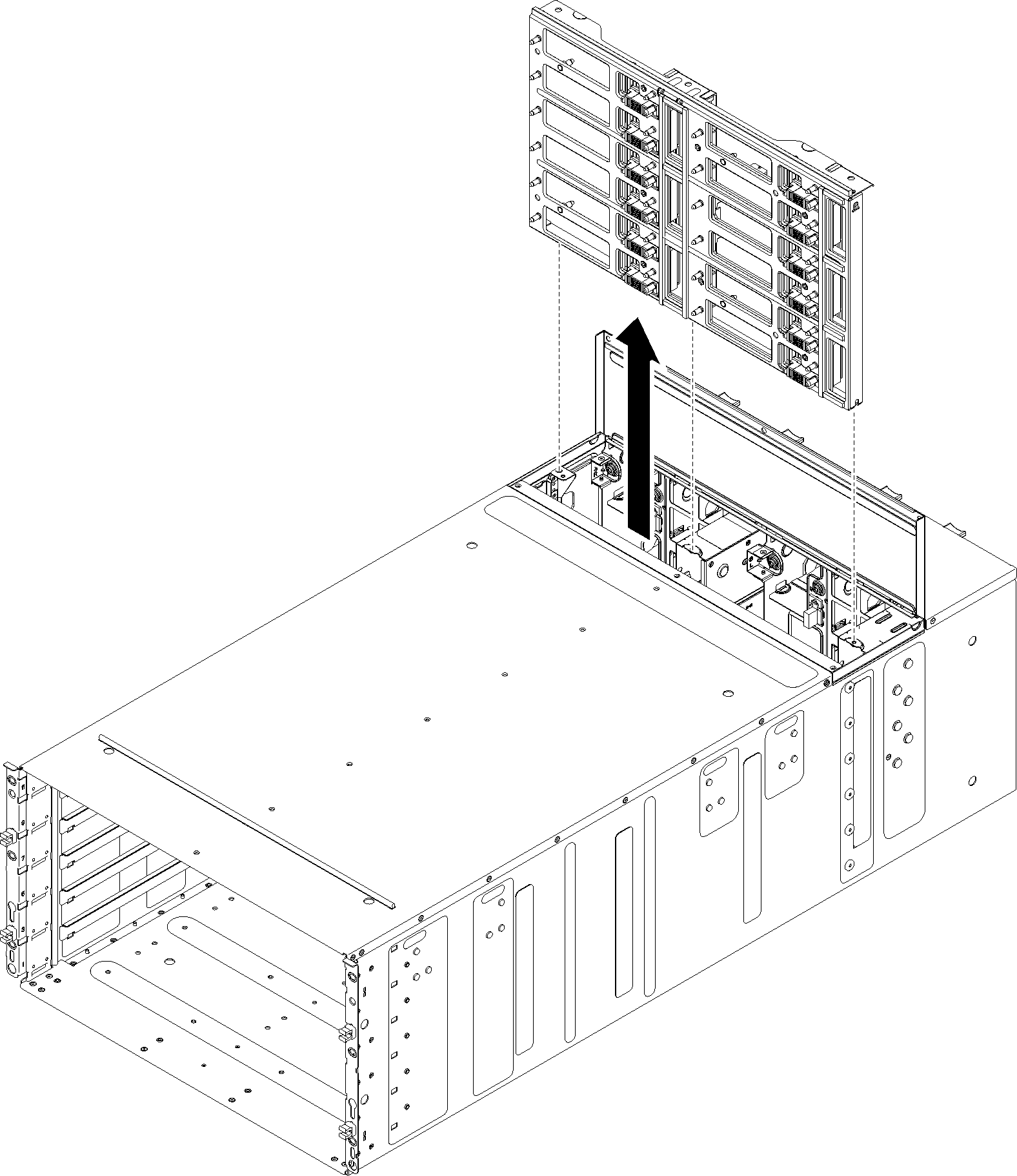
Remove all trays in the front of the enclosure (see Remove a DWC tray from the enclosure).
Remove all EMC shields on both sides.
Figure 1. Upper EMC shields removal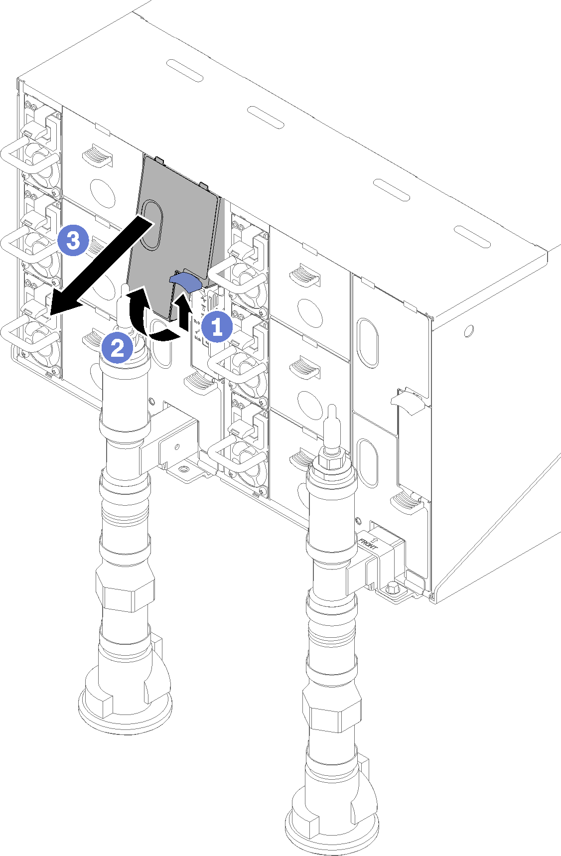 Figure 2. Lower EMC shields removal
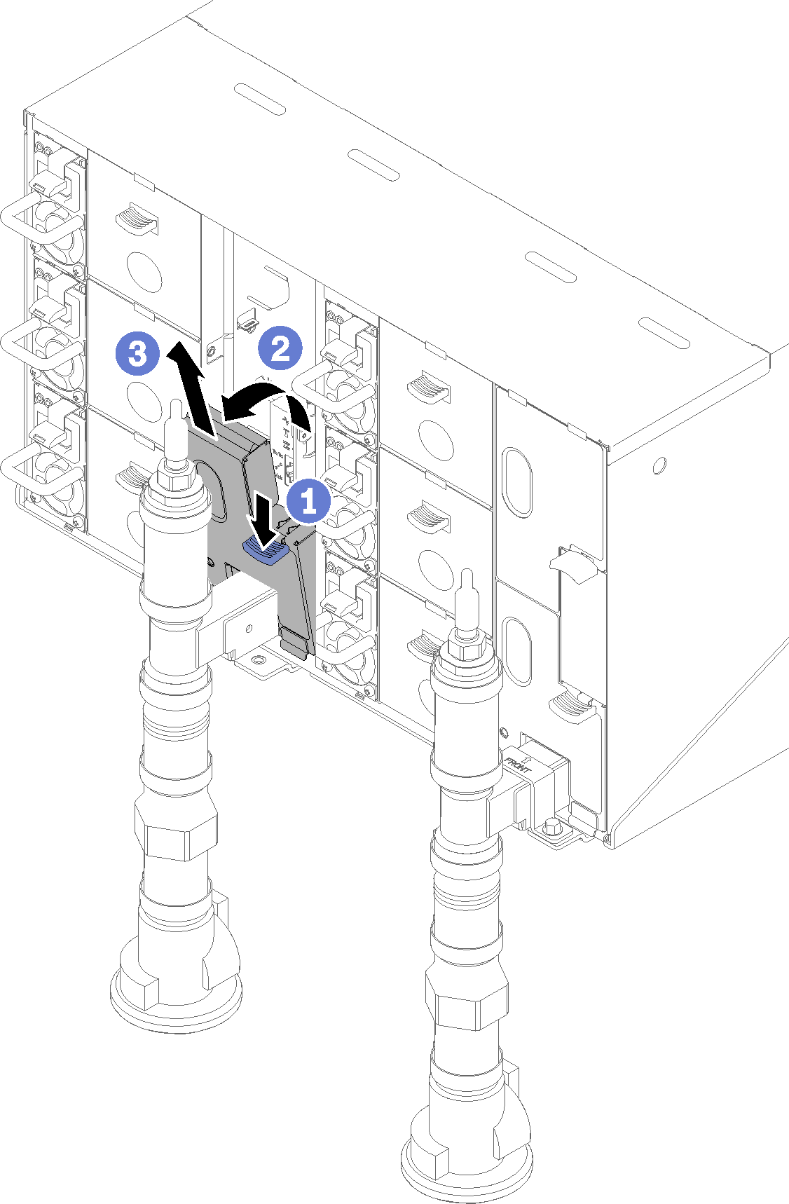
Push the latch up upwards and slide the drip sensor assembly backwards, then; lift the drip sensor assembly up to clear sensor post and pull it out of the enclosure.
Figure 3. Drip sensor assembly removal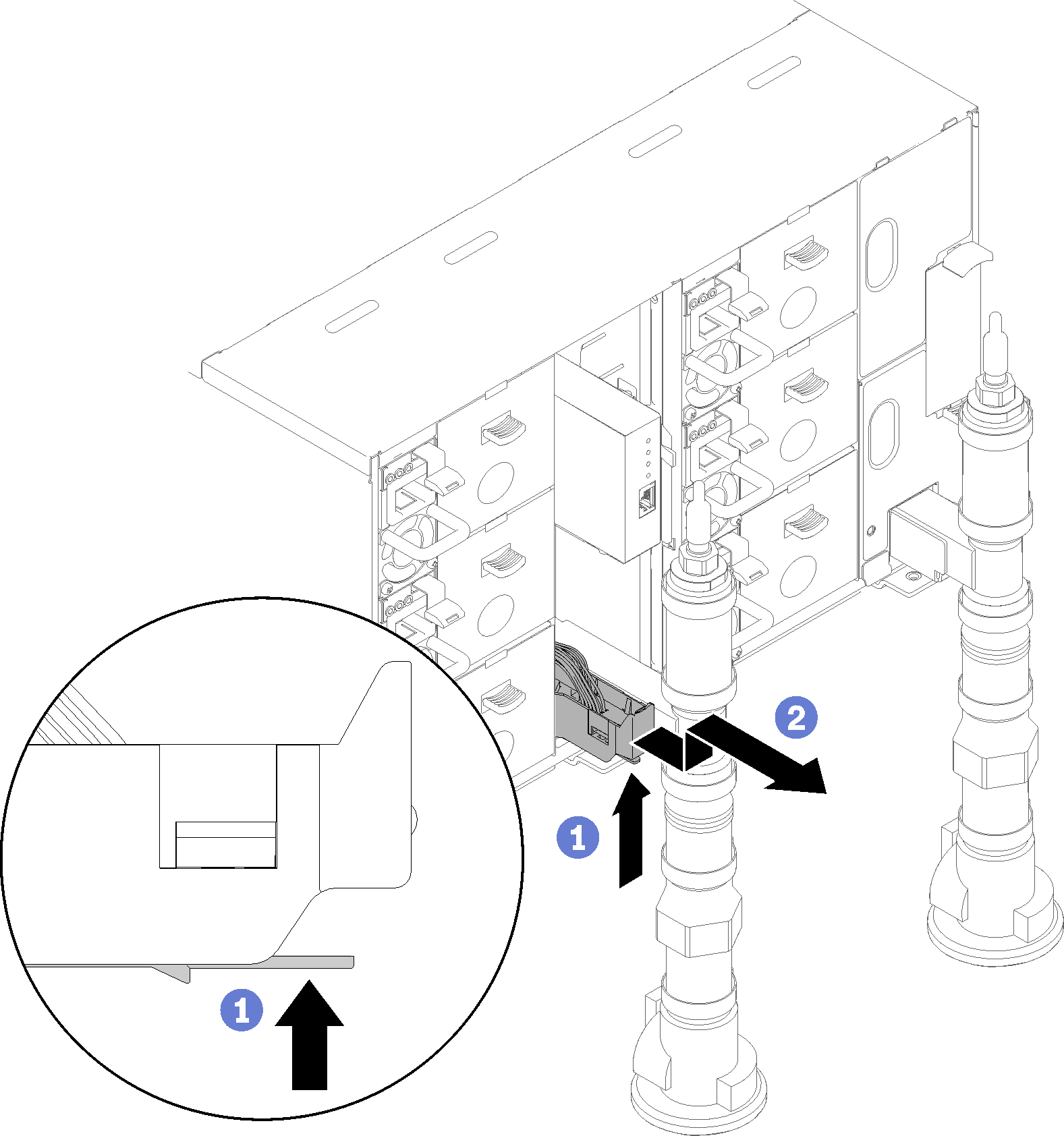
Remove manifold retention brackets that are retaining manifolds (top enclosure position only).
Figure 4. Retention bracket removal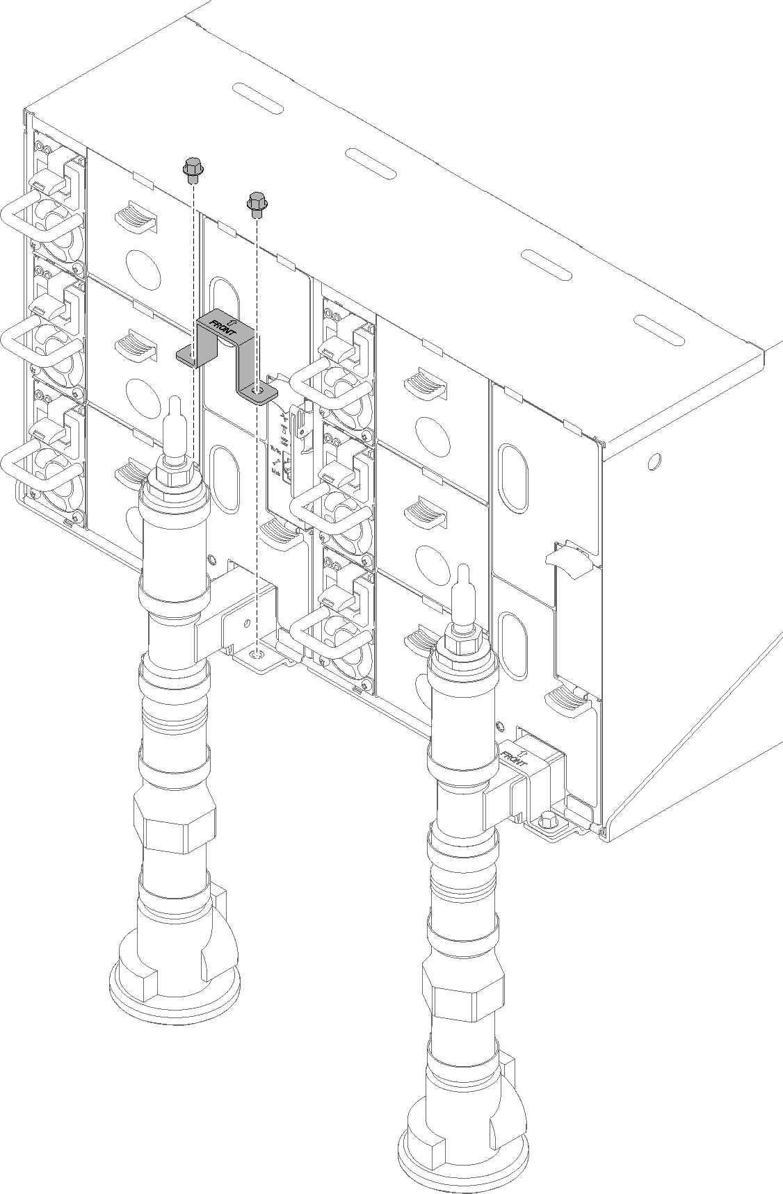
Remove FPC card module and FPC card module support bracket.
Figure 5. FPC card module removal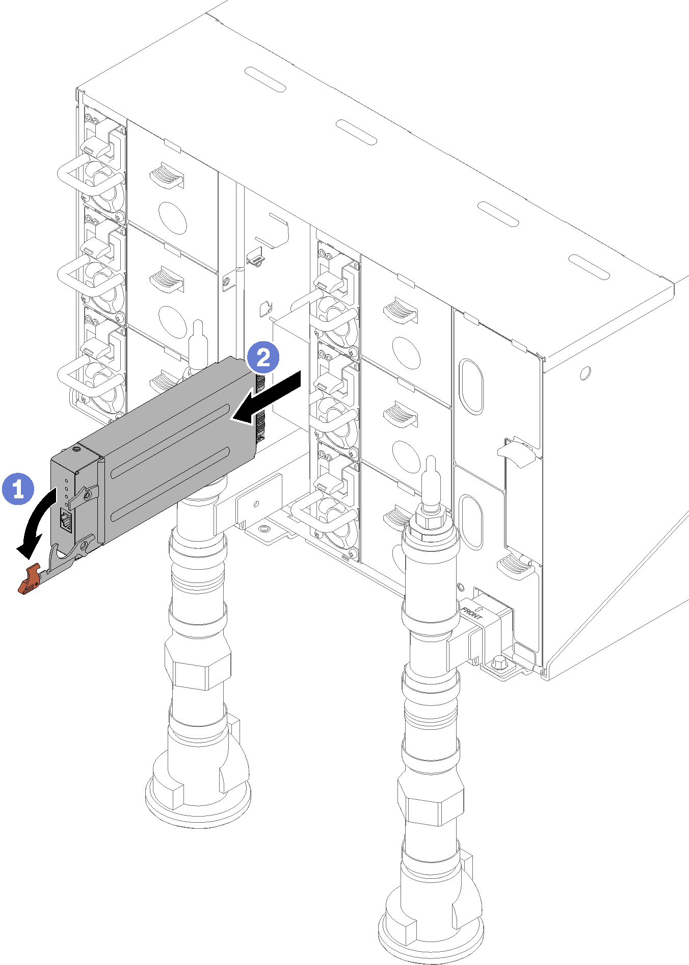 Figure 6. Support bracket removal
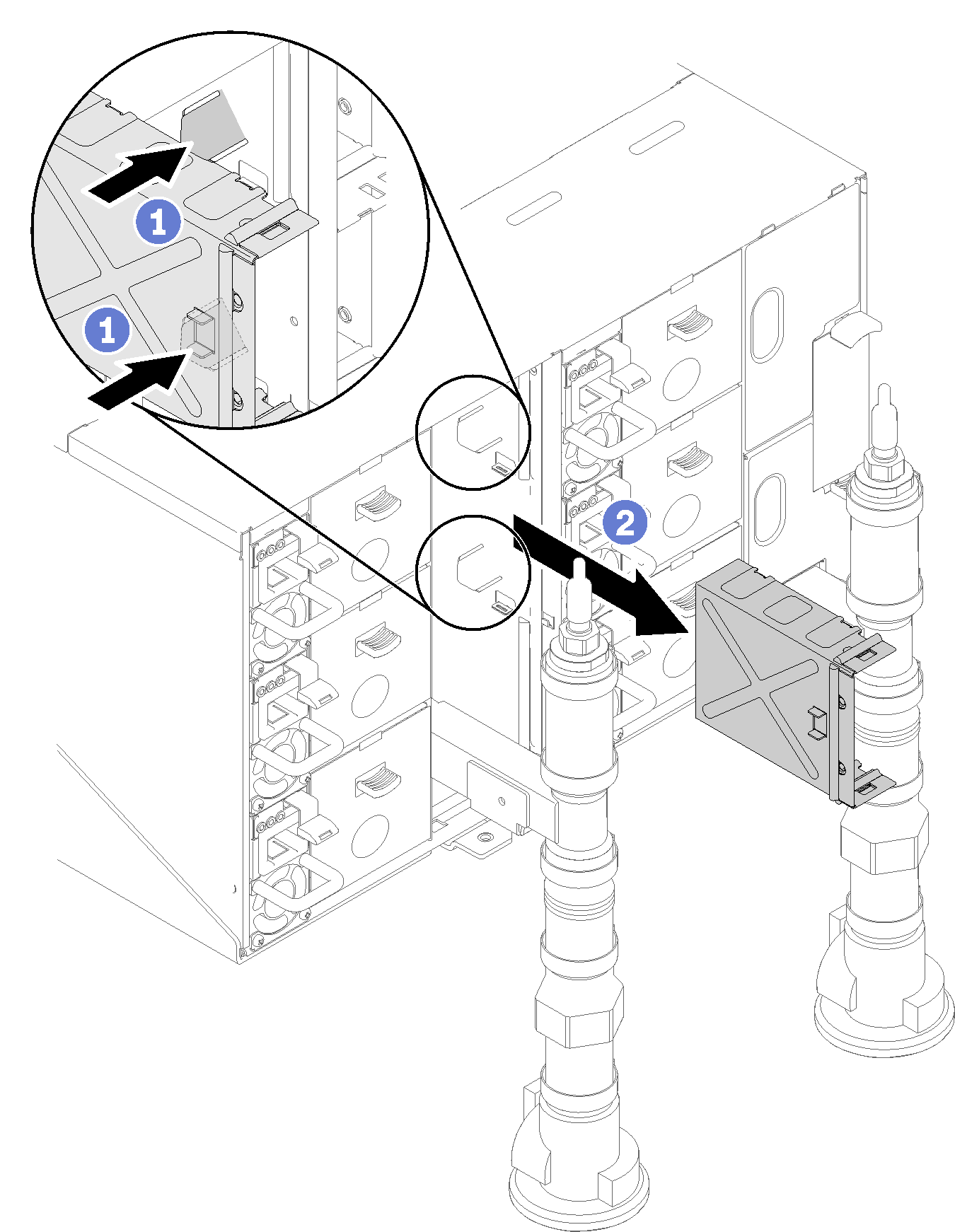
Remove the blank filler.
Figure 7. Blank filler removal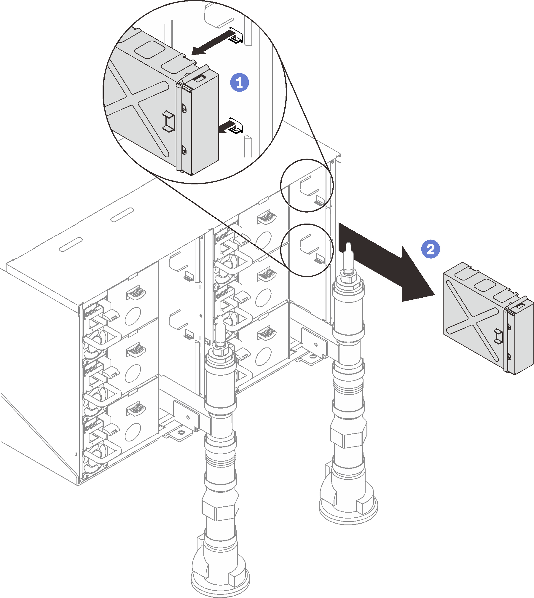
Remove all power supplies from the enclosure.
Figure 8. Power supply removal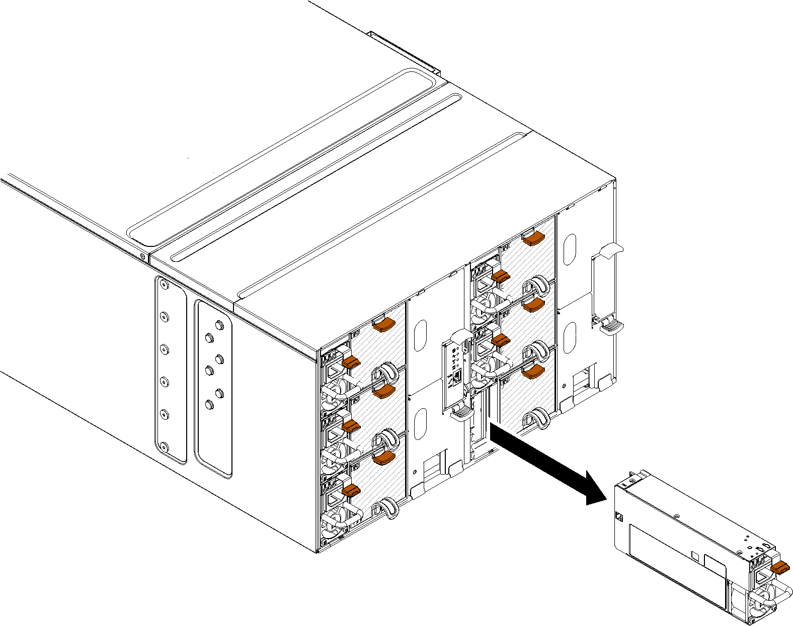
Remove eight screws (using the screwdriver contained in the manifold repair kit) to loosen two manifolds from the enclosure.
Figure 9. Manifold screw locations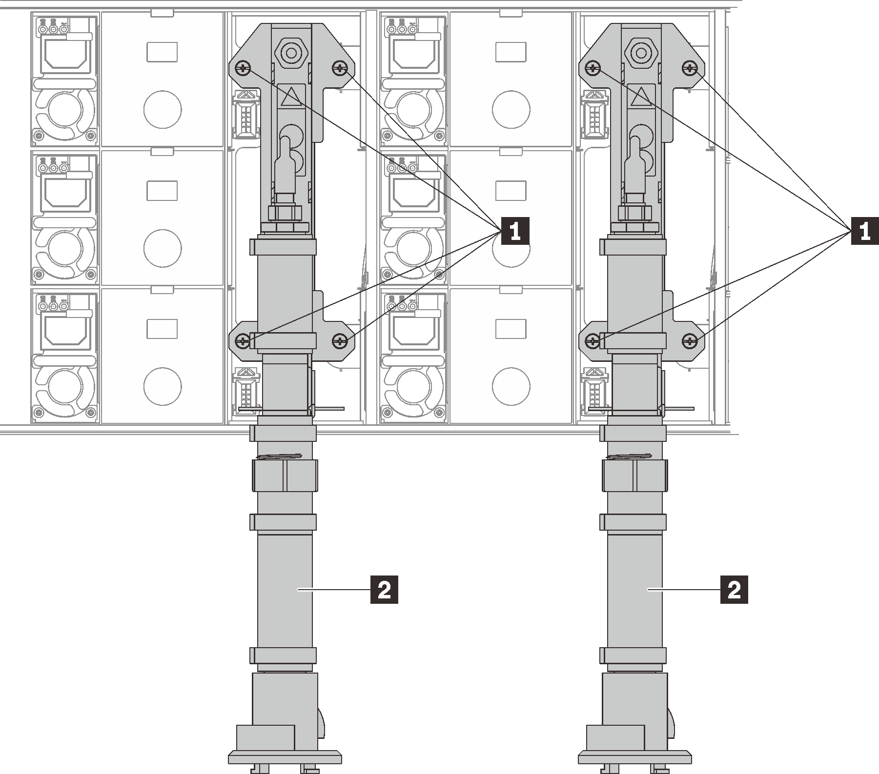
Table 1. Manifold screw locations 1 Screws 2 Manifold Remove eight screws to remove two support brackets on both sides.
Figure 10. Support bracket removal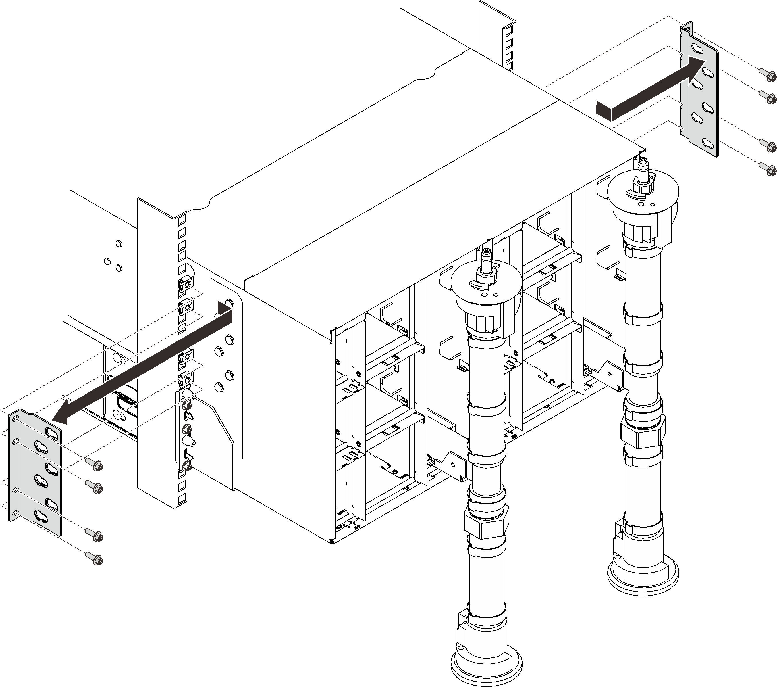
Remove two EIA covers at the front of the enclosure, then, remove six screws.
Figure 11. EIA cover removal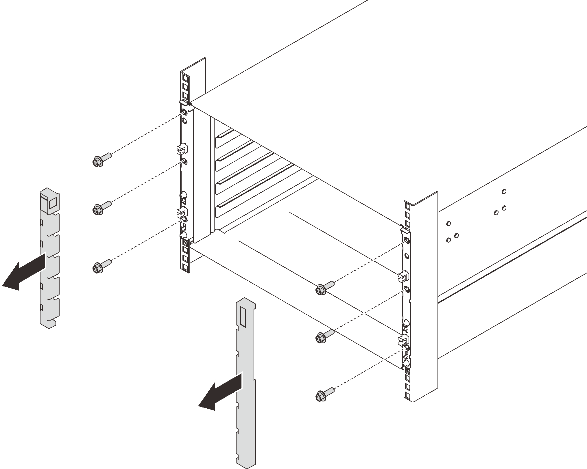
Slide the enclosure out until it allows you to attach front handles at both sides. Align slots on the handles with posts on the enclosure and slide handles up until them lock into places.
AttentionThree trained technicians are needed to complete the enclosure installation/removal task.Two technicians hold front and rear handles at both sides of the enclosure.
One technician protects cables from damage.
Figure 12. Sliding the enclosure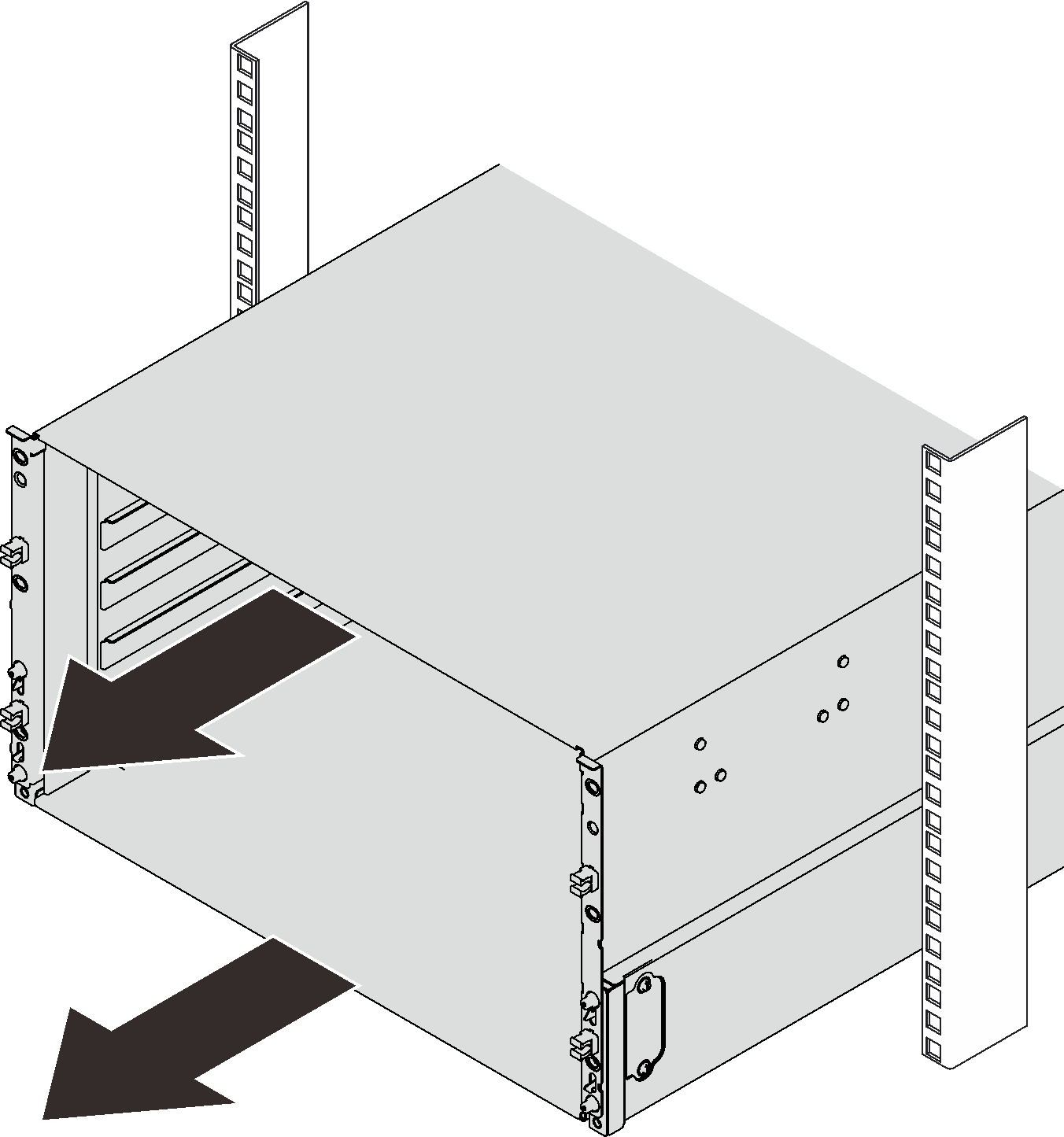 Figure 13. Front handle installation
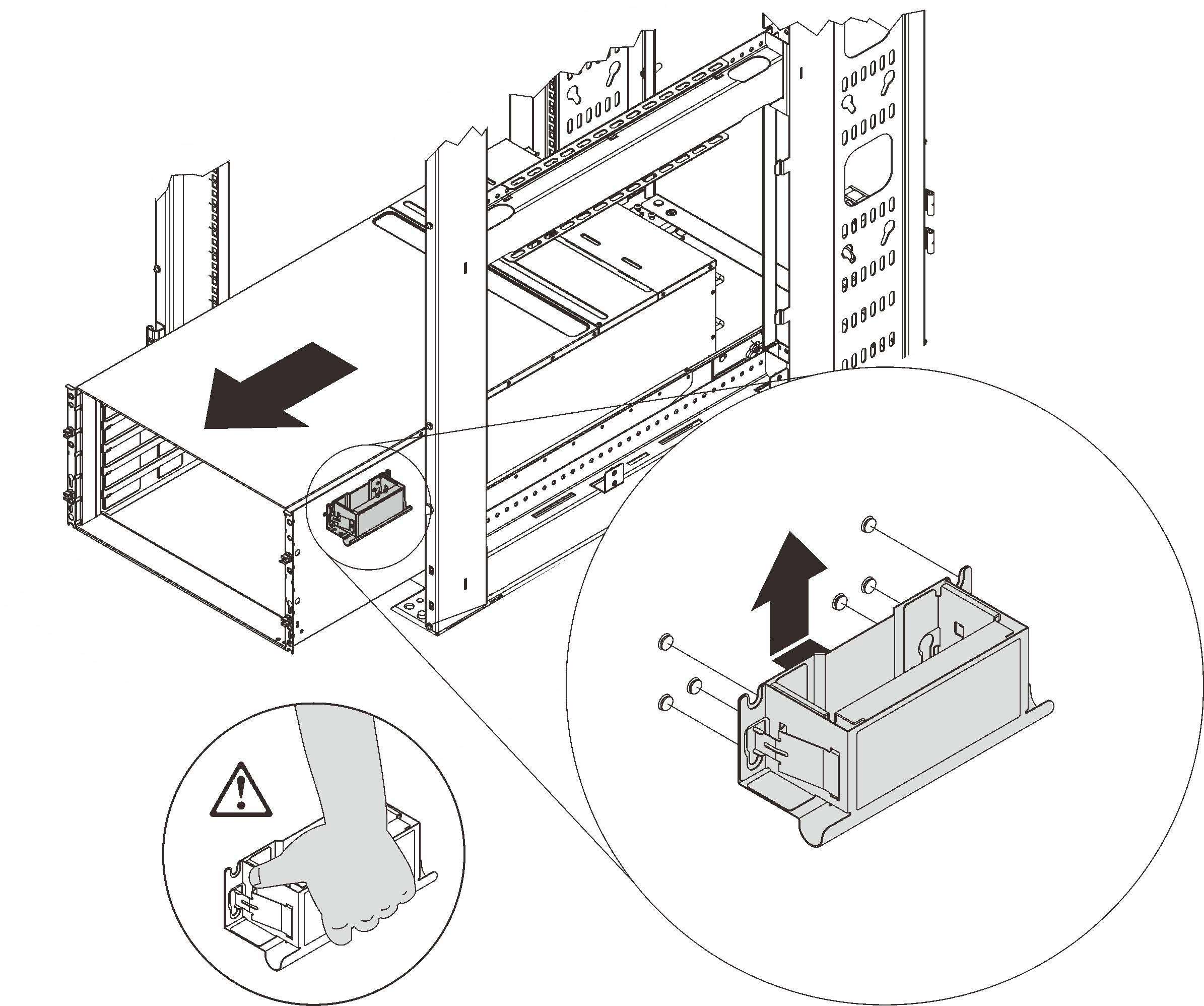
Hold front handles at both sides and slide the enclose out until you have enough space to install rear handles.
Figure 14. Rear handle installation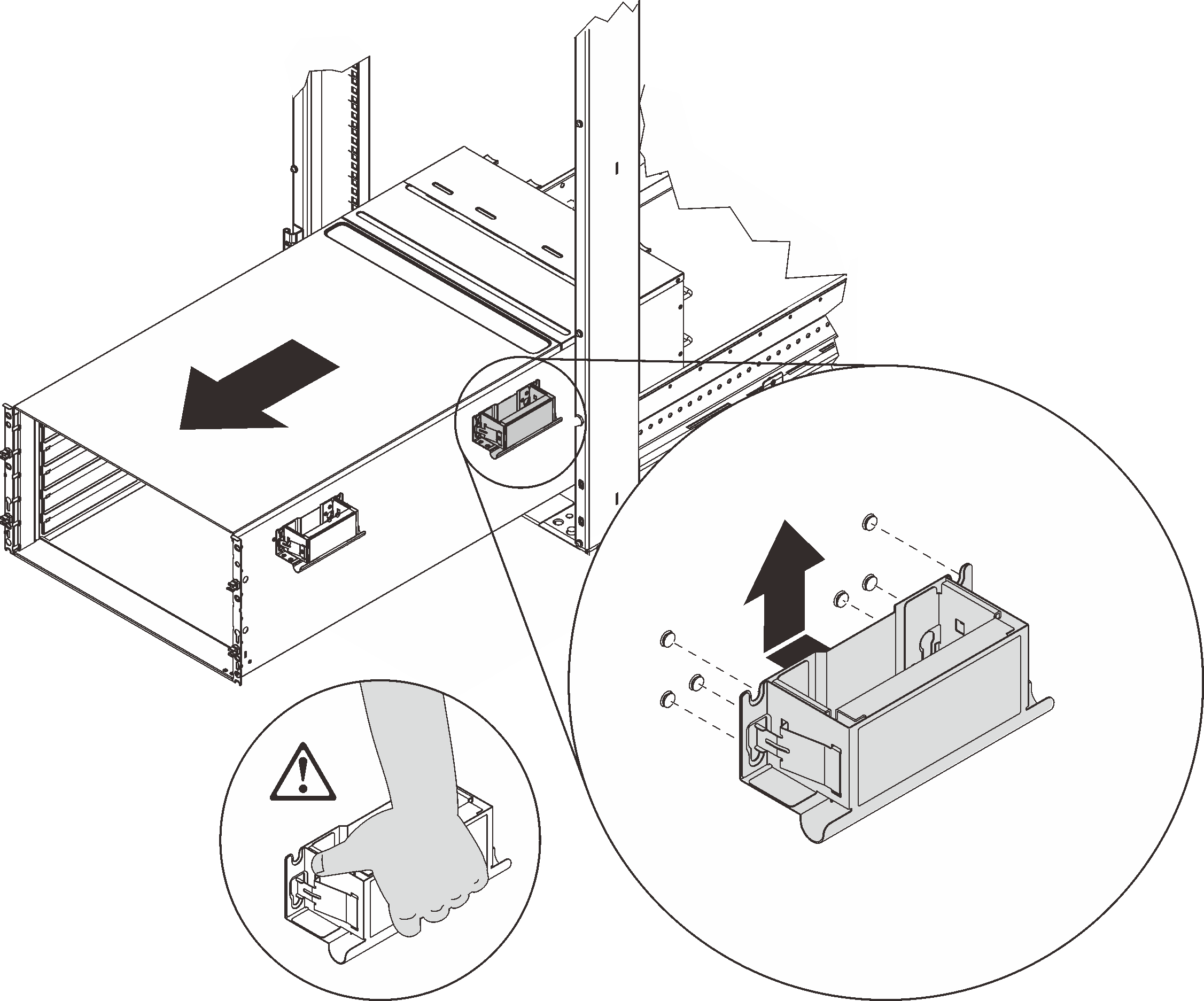
Carefully hold front and rear handles at both sides to slide the enclosure out of the rack; then, gently put the enclosure on a stable work surface.
Complete the following steps to remove the enclosure midplane.
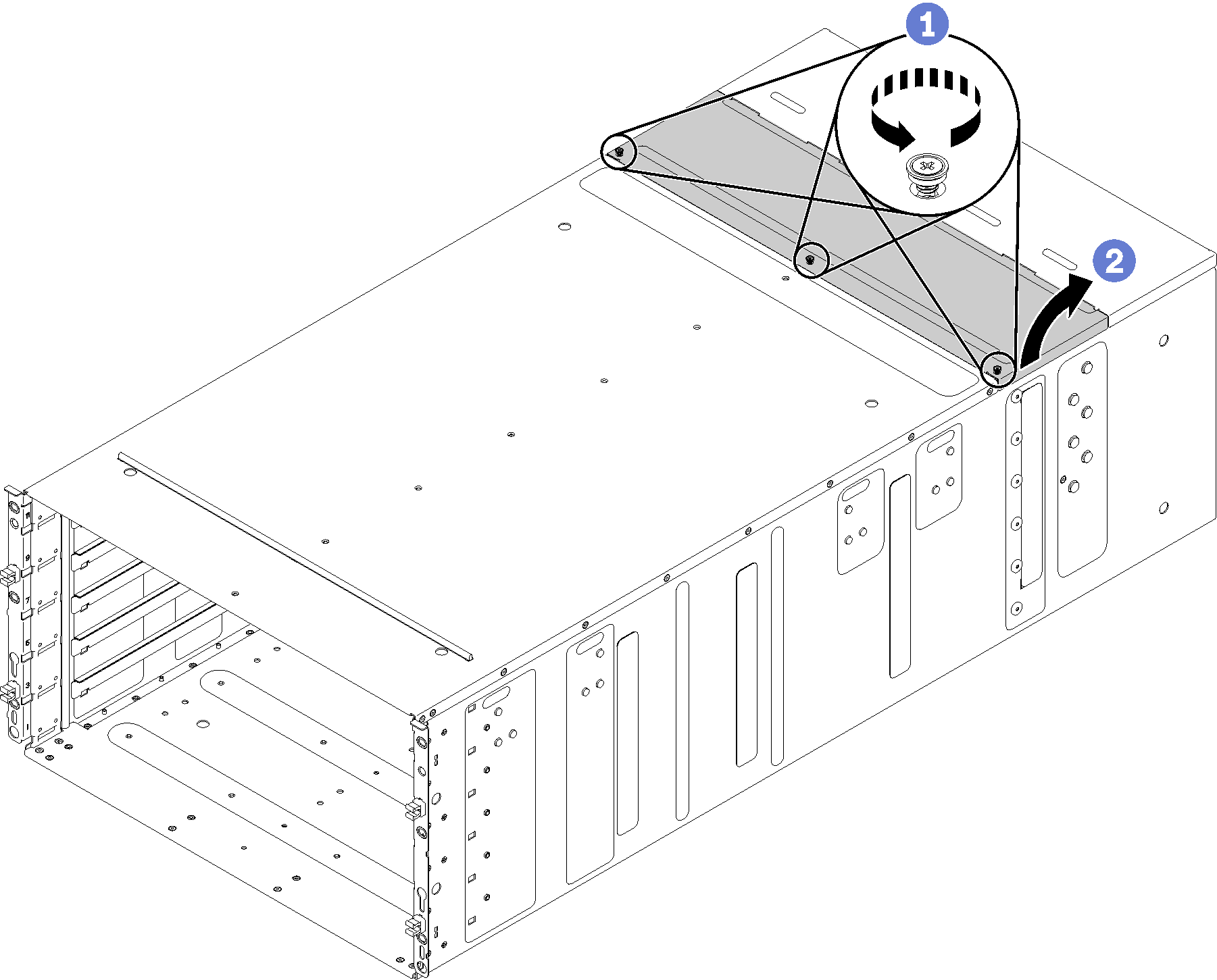
- Rotate the top cover outwards.Figure 15. Top cover outward rotation
- Lift up the enclosure midplane half way. Put a screwdriver or a stick in the middle of the enclosure midplane so your hands are free.Figure 16. Removal of the enclosure midplane from an enclosure
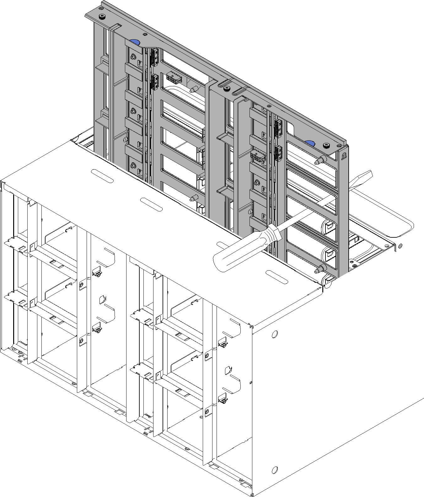
- Carefully grasp the enclosure midplane and slide it away from the enclosure.NoteMake sure that you do not grasp the connectors on the enclosure midplane. You could damage the connectors.Figure 17. Removal of the enclosure midplane from an enclosure
If you are instructed to return the component or optional device, follow all packaging instructions, and use any packaging materials for shipping that are supplied to you.
Demo video