System-board switches
The following illustration shows the location and description of the switches.
Important
- If there is a clear protective sticker on the switch blocks, you must remove and discard it to access the switches.
- Any system-board switch or jumper block that is not shown in the illustrations in this document are reserved.
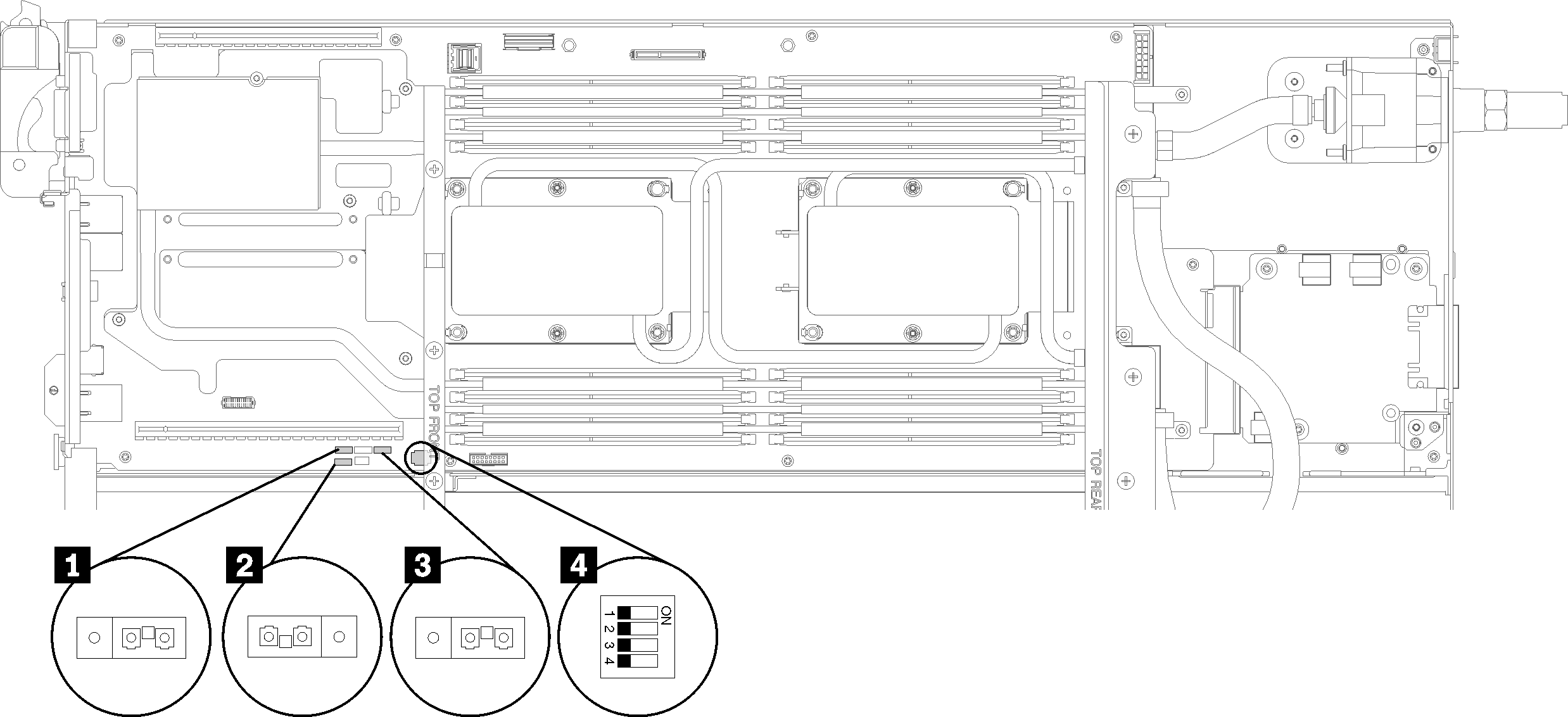
Figure 1. Location of the switches, jumpers, and buttons on the system board
The following table describes the jumpers on the system board.
| Jumper name | Description |
|---|---|
| 1 Low security |
|
| 2 Clear CMOS |
|
| 3 Serial select |
|
| Switch name | Switch number | Switch name | Usage description | |
|---|---|---|---|---|
| 4 PCH switch block - PCHSW1 | 1 | Machine Engine (ME) firmware security override | ME update by jumper. | Normal (default) |
| 2 | ME firmware update | Force update mode. | Normal (default) | |
| 3 | Password override | Overrides the power-on password. | Normal (default) | |
| 4 | Trusted Platform Module (TPM) physical presence | Indicates a physical presence to the system TPM. | Normal (default) | |
Important
- Before you change any switch settings or move any jumpers, turn off the solution; then, disconnect all power cords and external cables. Review the information in Safety Information page, Installation Guidelines, Handling static-sensitive devices, and Power off nodes.
- Any system-board switch or jumper block that is not shown in the illustrations in this document are reserved.
Give documentation feedback