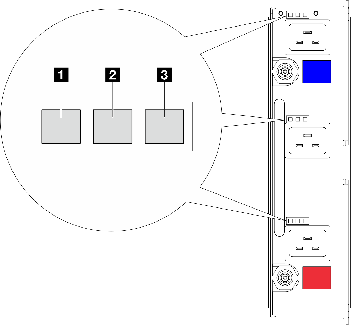
DWC power supply LEDs
This topic provides information about various DWC power supply LED status and corresponding action suggestions.
The following minimal configuration is required for the solution to start:
One DW612S Enclosure
One SD665-N V3 tray
Two processors on the compute node
One NVIDIA HGX H100 4-GPU board and network board (4 Connect-X 7)
2 DIMMs per node in slot 6 and slot 19. (one DIMM per processor)
Two CFF v4 power supplies or one DWC PSU
One drive (any type) (If OS is needed for debugging)
The power supplies get electrical power from a 200 - 240 V ac power source and convert the ac input into 12 V outputs. The power supplies are capable of autoranging within the input voltage range. There is one common power domain for the enclosure that distributes power to each of the DWC tray and modules through the system midplane.
AC redundancy is achieved by distributing the ac power cord connections between independent ac circuits.
Each DWC power supply has internal water loops and a controller. The power supply controller can be powered by any installed power supply that is providing power through the midplane.
You have to install all three DWC power supplies regardless of the type of power supply, the enclosure power load, or selected enclosure power policy.
The enclosure does not support mixing of low input voltage power supplies with high input voltage power supplies. For example, if you install a power supply with an input voltage of 100 - 127 V ac in a enclosure that is powered by 200 - 240 V ac power supplies, the 100 - 127 V power supply will not power on. The same restriction applies to a enclosure that is powered by 100 - 127 V ac power supplies. If you install a 200 - 240 V ac power supply in a enclosure that is powered by 100 - 127 V ac power supplies, the 200 - 240 V ac power supply will not power on.
The following illustration shows the LEDs on the DWC power supply:

| 1 Input (AC) power LED (green) | 3 Power supply error LED (yellow) |
| 2 Output (DC) power LED (green) |
There are nine LEDs on each DWC power supply (three per power supply bay):
1 AC power LED (green): When this LED is lit (green), it indicates that ac power is being supplied to the DWC power supply in the corresponding power supply bay.
2 DC power LED (green): When this LED is lit (green), it indicates that dc power is being supplied from the corresponding power supply bay to the enclosure midplane.