Top view
This section contains information on the top view of the solution.
Compute node top view
Figure 1. Compute node top view
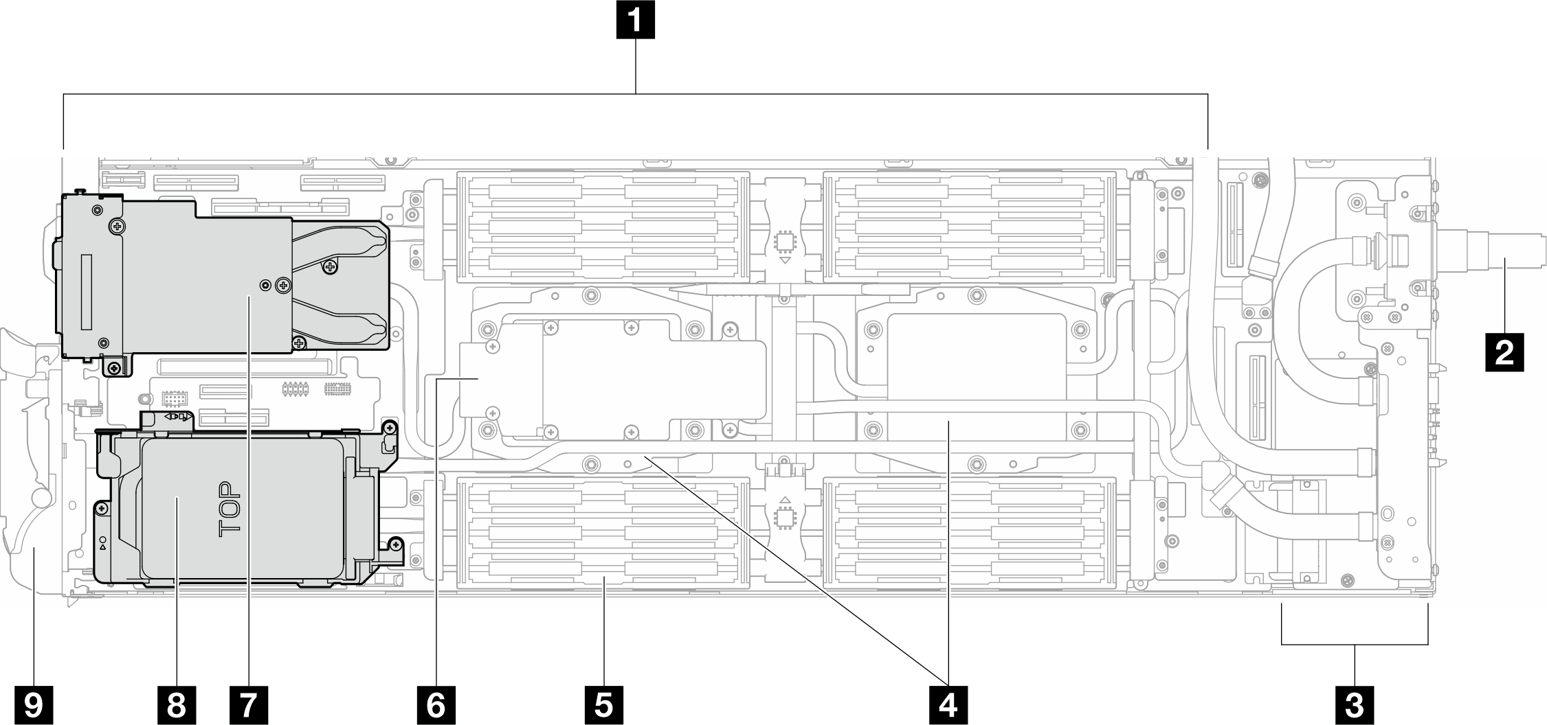
| 1 System board | 6 M.2 drive backplane |
| 2 Water loop quick connect | 7 OSFP module See Hardware replacement procedures for component replacement. |
| 3 Power distribution board | 8 Drive bay 2/3 See Hardware replacement procedures for component replacement. |
| 4 Processor cold plates | 9 Front cam handle |
| 5 Memory module cooling tube |
GPU node top view
Figure 2. GPU node top view
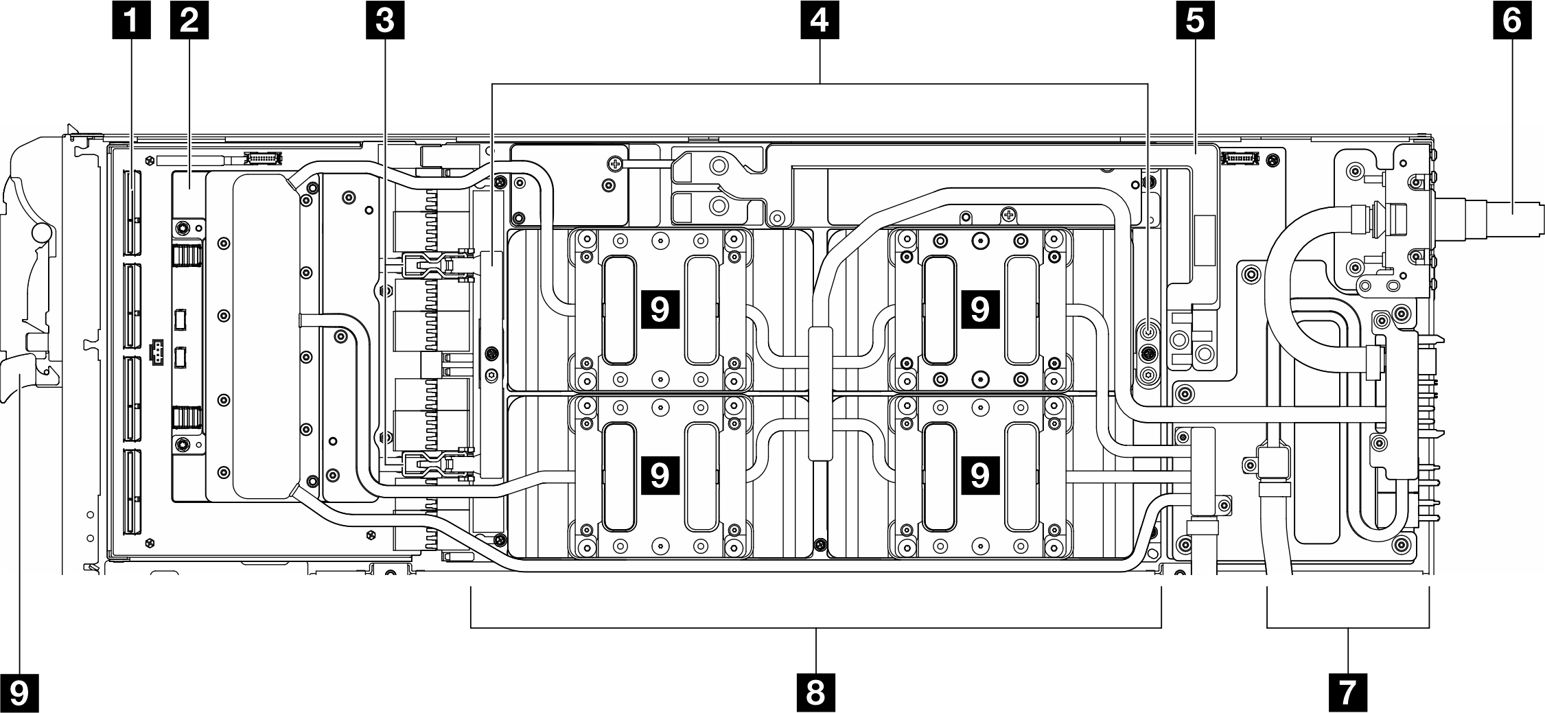
| 1 Carrier board (for network board) | 6 Water loop quick connect |
| 2 Network board | 7 GPU node power distribution board |
| 3 Carrier board retention clips | 8 GPU board |
| 4 GPU board handles | 9 GPUs |
| 5 Bus bar |
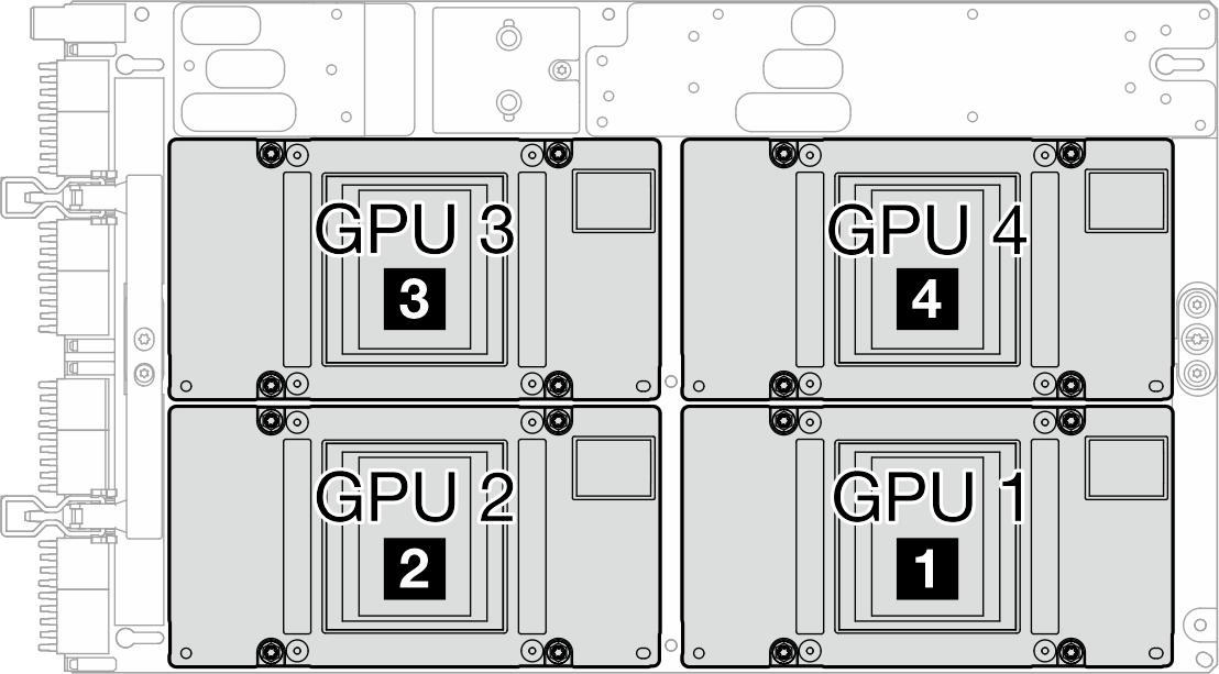
GPU numbering
The following illustration shows the GPU numbering.
Figure 3. GPU numbering
Give documentation feedback