System-board switches
The following illustration shows the location and description of the switches.
Important
Before you change any switch settings or move any jumpers, turn off the solution; then, disconnect all power cords and external cables. Review the following information:
Safety information for ThinkSystem server: Safety Information page
- Any system-board switch or jumper block that is not shown in the illustrations in this document are reserved.
Note
If there is a clear protective sticker on the top of the switch blocks, you must remove and discard it to access the switches.
Figure 1. Switches on compute node system board
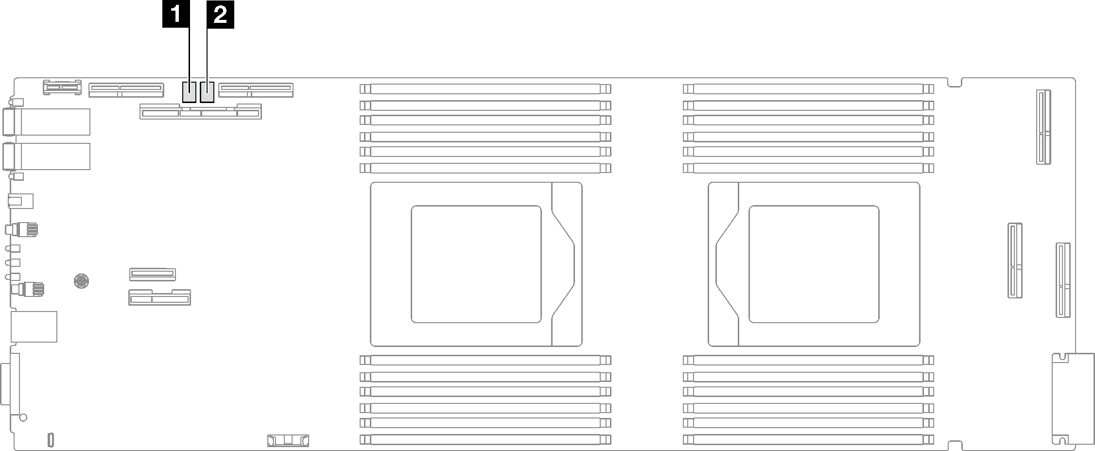
| 1 SW5 switch block | 2 SW11 switch block |
| Switch number | Switch name | Usage description | |
|---|---|---|---|
| On | Off | ||
1 | XCC reset | Force hot reset BMC chip | Normal (default) |
3 | XCC boot primary | Request XCC to boot from backup bank | Request XCC to boot from primary bank (default) |
4 | Password override | Overrides the power-on password | Normal (default) |
| Switch number | Switch name | Usage description | |
|---|---|---|---|
| On | Off | ||
3 | Clear CMOS | Clear CMOS data | Normal (default) |
Give documentation feedback