PCIe adapter in compute node cable routing
Use this information to route the cables for PCIe adapters in the compute node.
PCIe adapter configuration and cable routing
Balanced I/O configuration
Balanced I/O configuration is supported by the following PCIe adapters:
ConnectX-6
ConnectX-7 NDR 200
ConnectX-7 NDR 400
CN5000
Figure 1. Balanced I/O configuration
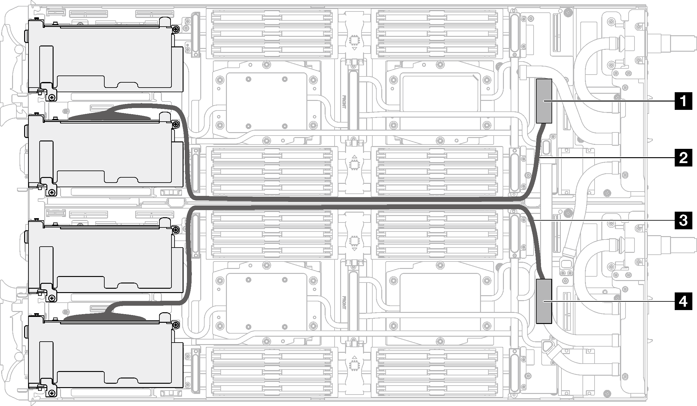
| System board connectors and cables | Node |
|---|---|
| 1 PCIe 1/SATA – PCIe x16 Gen 5 connector | Left node |
| 2 640 mm PCIe cable (direct-soldering on PCIe slot 1) | |
| 3 660 mm PCIe cable (direct-soldering on PCIe slot 1) | Right node |
| 4 PCIe 1/SATA – PCIe x16 Gen 5 connector |
Shared I/O configuration
Shared I/O configuration for the following PCIe adapters:
Note
In shared I/O configuration, when the main node performs virtual reseat, aux node’s XCC web GUI will show the warning message FQXSFIO0021J to indicate that PCIe error recovery has occurred and the adapter may not operate correctly. To solve this issue, restart the aux node. For additional user actions, see Event Message: FQXSFIO0021J.
ConnectX-6
ConnectX-7 NDR 200
ConnectX-7 NDR 400
Figure 2. Shared I/O configuration
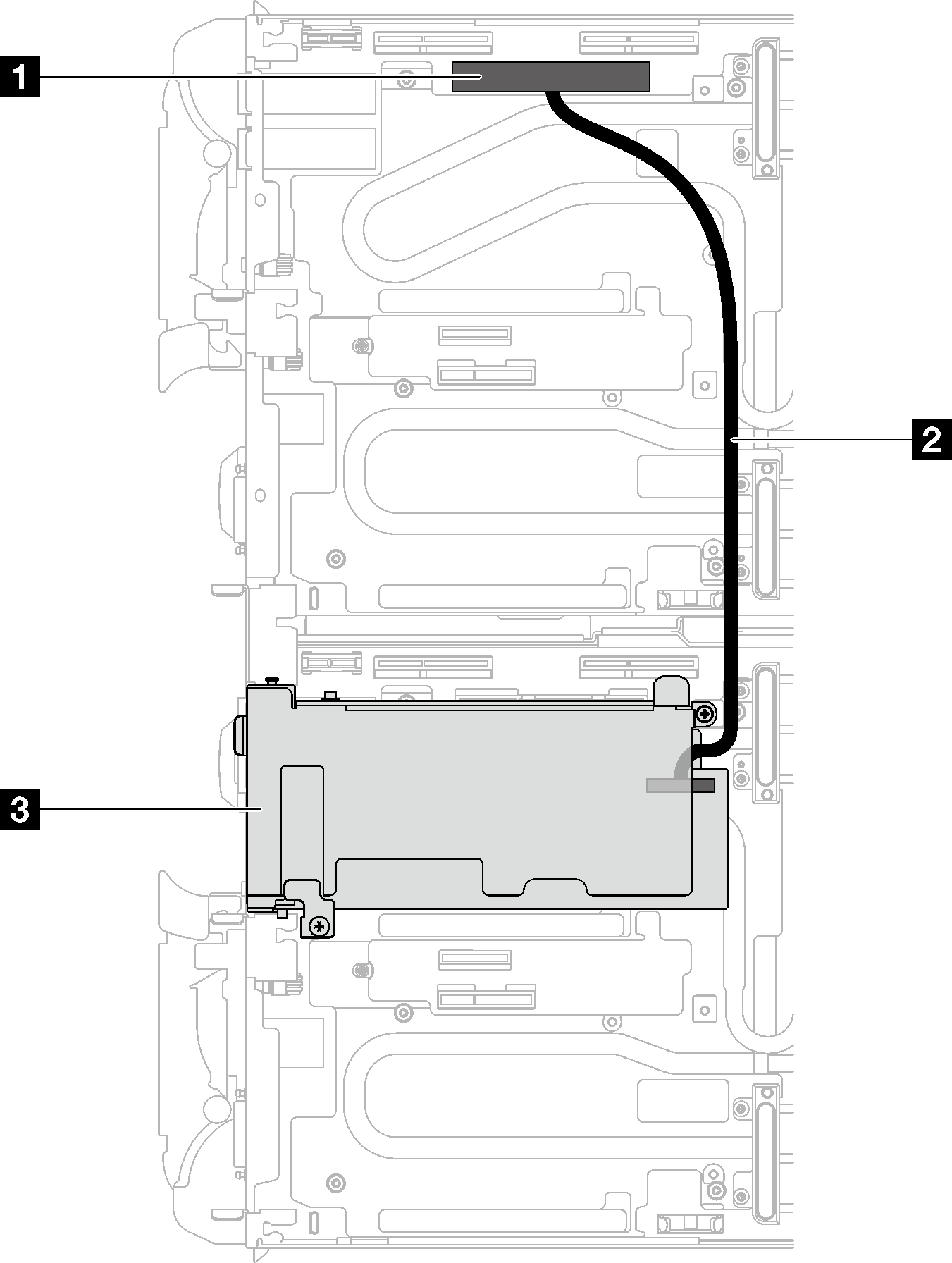
| Component index | Node |
|---|---|
| 1 PCIe 2 – PCIe x16 connector | Left node |
| 2 310 mm interconnect cable | From left node to PCIe adapter in right node. |
| 3 PCIe slot 2 | Right node |
Socket direct configuration (ConnectX-7 NDR 400)
Socket direct configuration is supported by the following PCIe adapters:
Note
In shared I/O configuration, when the main node performs virtual reseat, aux node’s XCC web GUI will show the warning message FQXSFIO0021J to indicate that PCIe error recovery has occurred and the adapter may not operate correctly. To solve this issue, restart the aux node. For additional user actions, see Event Message: FQXSFIO0021J.
ConnectX-7 NDR 400
Figure 3. Socket direct configuration cable routing
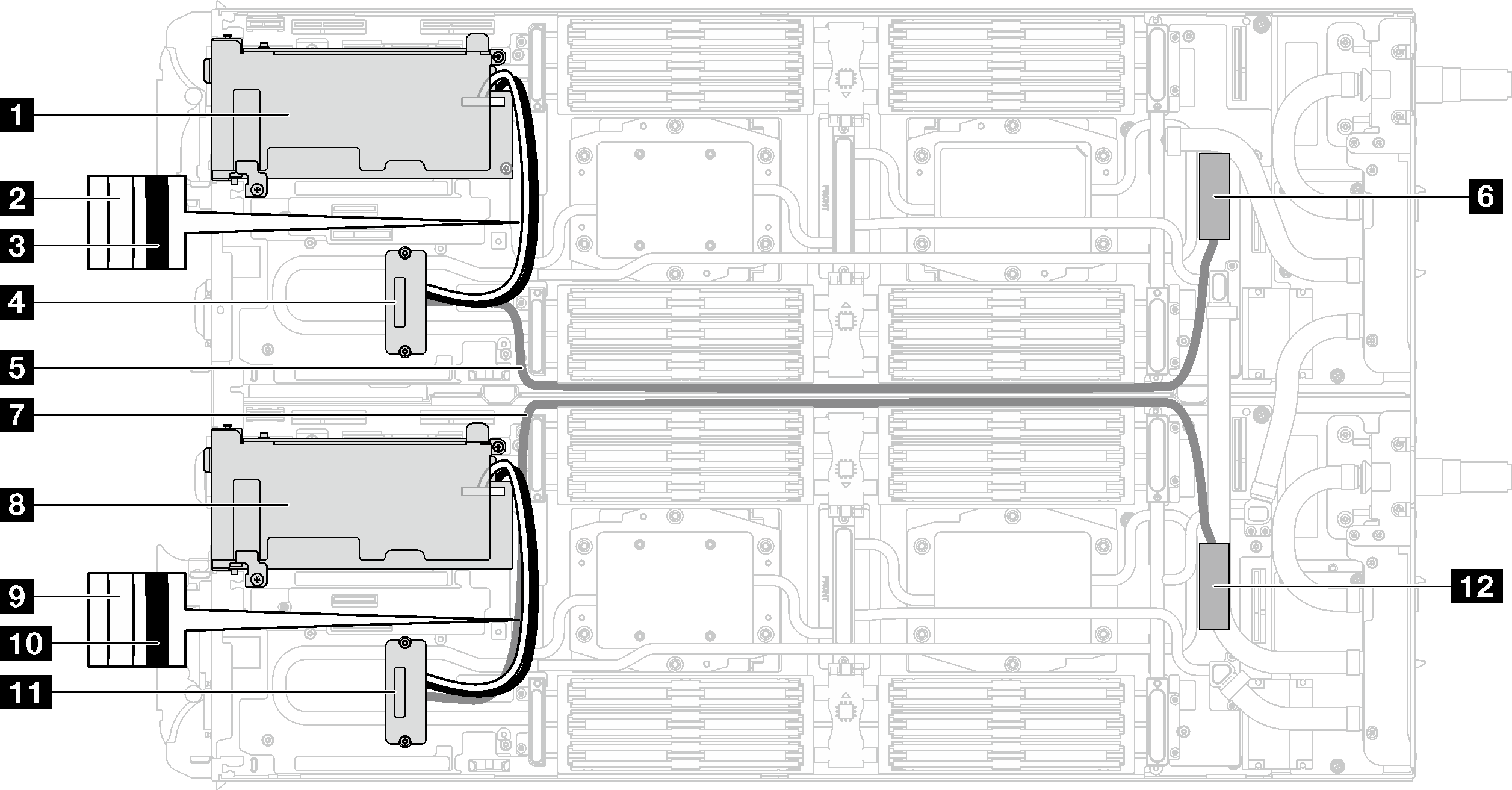
| Component index | Node |
|---|---|
| 1 PCIe slot 2 | Left node |
| 2 200 mm interconnect cable (white, connected to the connector marked as “white” on the PCIe adapter) | |
| 3 200 mm interconnect cable (black, connected to the connector marked as “black” on the PCIe adapter) | |
| 4 Interposer installed on water loop cold plate | |
| 5 745 mm PCIe cable | |
| 6 PCIe 1/SATA – PCIe x16 connector | |
| 7 745 mm PCIe cable | Right node |
| 8 PCIe slot 2 | |
| 9 200 mm interconnect cable (white, connected to the connector marked as “white” on the PCIe adapter) | |
| 10 200 mm interconnect cable (black, connected to the connector marked as “black” on the PCIe adapter) | |
| 11 Interposer installed on water loop cold plate | |
| 12 PCIe 1/SATA – PCIe x16 connector |
Give documentation feedback