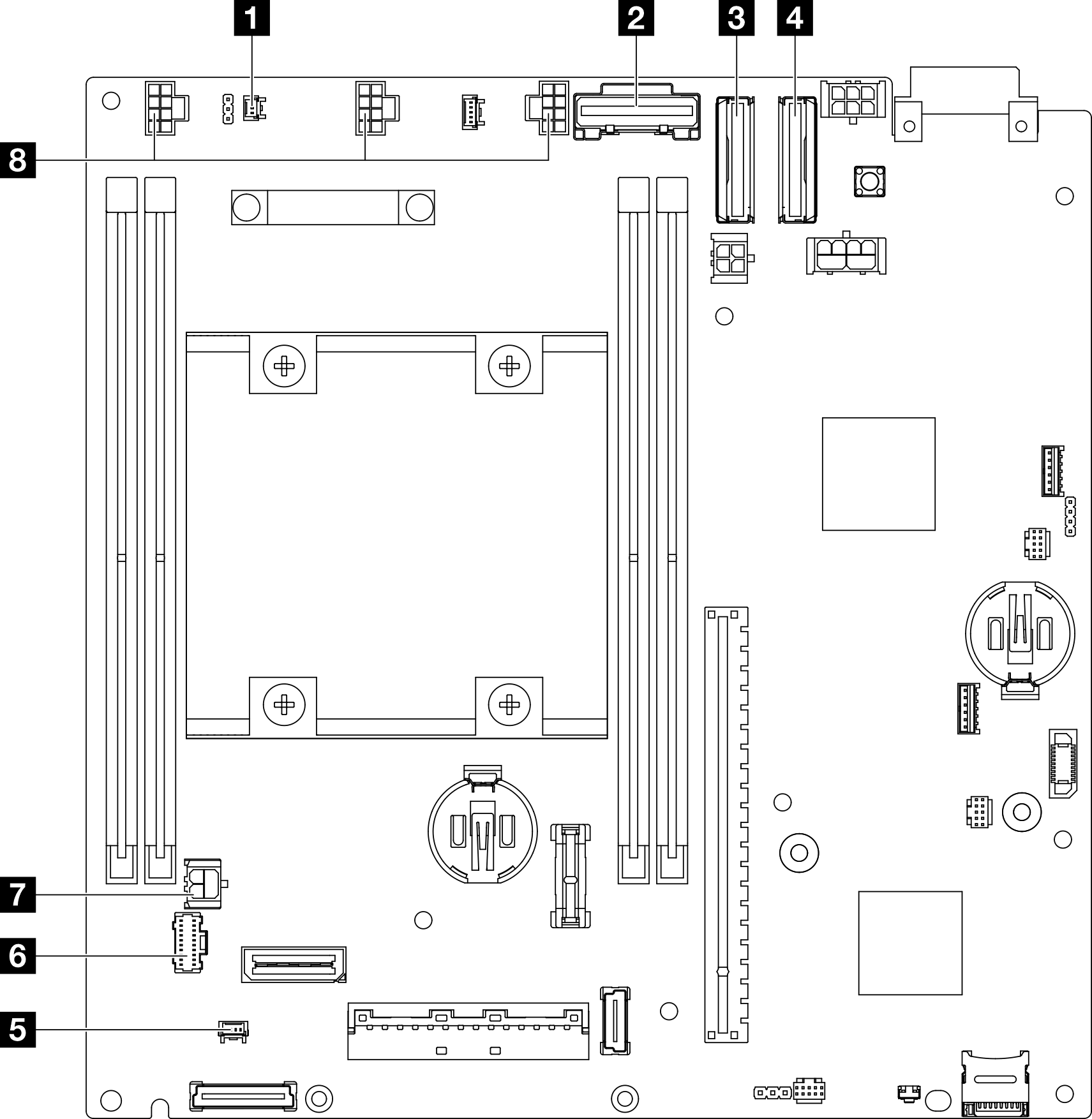
System-board connectors for cable routing
The following illustration shows the internal connectors on the system board that are used for internal cable routing.
Figure 1. System-board connectors for cable routing


| 1 Connector for the intrusion switch cable* | 5 Connector for the lock position switch cable* |
| 2 SATA connector for Drive backplane 1 (lower) | 6 Connector for the front operator assembly |
| 3 MCIO connector 1 for Drive backplane 1 (lower) | 7 Power connector for the I/O module board |
| 4 MCIO connector 2 for Drive backplane 2 (upper) | 8 Connectors for fan cables* |
Note
- * For the installation or removal of the intrusion switch with cable, see Intrusion switch with cable replacement.
- * For the installation or removal of the lock position switch with cable, see Keylock switch with cable replacement.
- * For the installation or removal of the fan cables, see Fan module replacement.
Give documentation feedback