The front operator panel and error LEDs
The front operator panel is a system of LEDs on various external and internal components of the server that leads you to the failed component. When an error occurs, LEDs are lit on the front operator panel on the front of the server, then on the failed component. By viewing the LEDs in a particular order, you can often identify the source of the error.
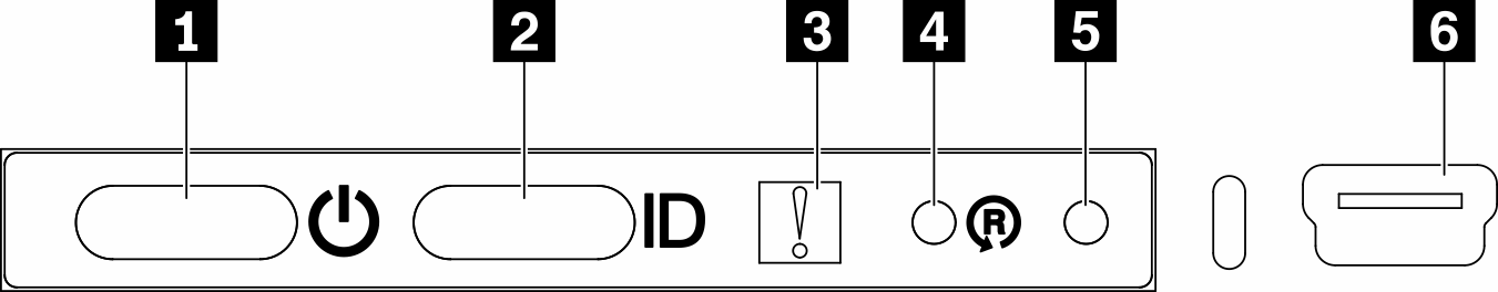
| 1 Power button/LED (green) | 4 Wireless enabled LOM package reset button |
| 2 Identification button/LED (blue) | 5 NMI button |
| 3 System-error LED (yellow) | 6 XClarity Controller mini USB connector |
- Off: Power is not present or the power adapter, or the LED itself has failed.
- Flashing rapidly (4 times per second): The server is turned off and is not ready to be turned on. The power button is disabled. This will last approximately 5 to 10 seconds.
- Flashing slowly (once per second): The server is turned off and is ready to be turned on. You can press the power button to turn on the server.
- On: The server is turned on.
2 Identification button/LED (blue): Use this blue LED to visually locate the server among other servers. This LED is also used as a presence detection button. You can use Lenovo XClarity Administrator to light this LED remotely.
3 System-error LED (yellow): When this yellow LED is lit, it indicates that a system error has occurred. A system-error LED is also on the rear of the server. Messages on the LCD system information display panel and LEDs on other server components might also be lit to help isolate the error. This LED is controlled by the Lenovo XClarity Controller.
4 Wireless enabled LOM package reset button: Press this pinhole to reset the network SoC (use this button only when directed by the service support). You have to use the end of a straightened paper clip to press the pinhole.
5 NMI button: Press this pinhole to force a non-maskable interrupt to the processor. It allows you to blue screen the solution and take a memory dump (use this button only when directed by the service support). You have to use the end of a straightened paper clip to press the pinhole.
6 XClarity Controller mini USB connector: The connector provides direct access to Lenovo XClarity Controller management.