Wireless enabled LOM package preset
Use this information to apply preset configuration of wireless enabled LOM package.
Setting up the network topology
A network topology is an arrangement of network in which all nodes connect with each other using network links. Several network topologies presets have been defined to facilitate port assignment of the server. Depends on usage scenario, server can operate as a standalone system or as a cluster with other peer servers.
There are six types of network topology available for chosen (configuration 1-5 are preset, configuration 6 is available for customized).
- Lenovo XClarity Controller: select topology type in Edge Networking
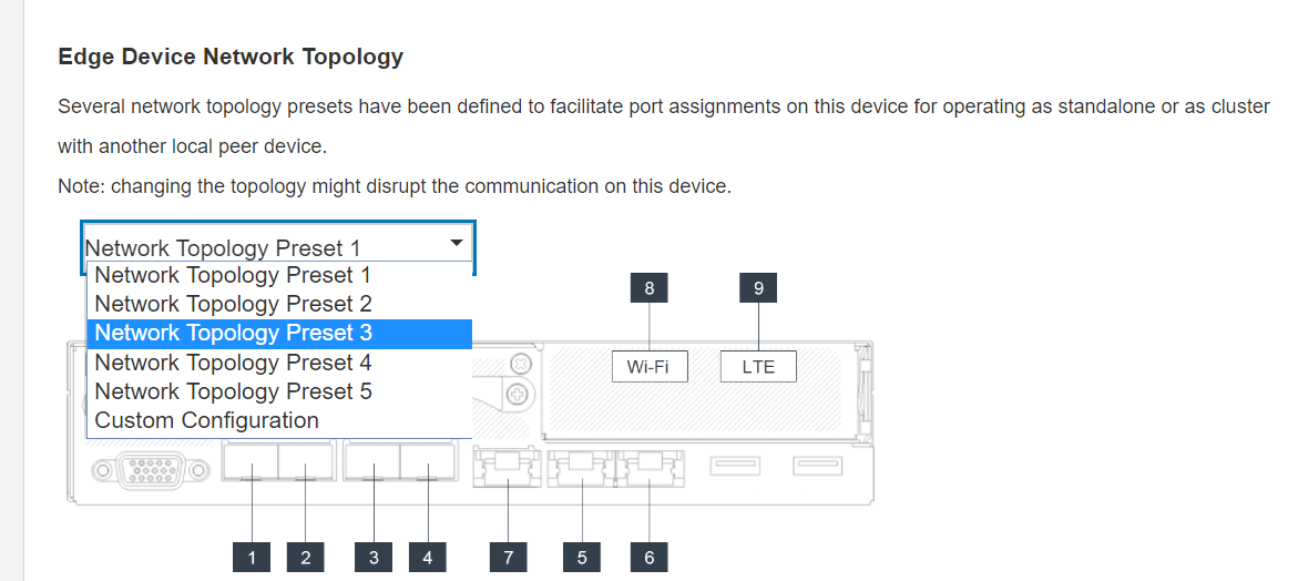
Embedded Switch CLI (access through SSH): use command sudo set_topology 1
Change topology by changing the number in the command. Number could be 1-6. Noted that topology 6 could only be used after customized setting had been created.
LTE/WLAN and IPMI over KCS Access are disabled by default, it is required to enable them through XCC.
System resets the network settings of ports to default after users change network topology.
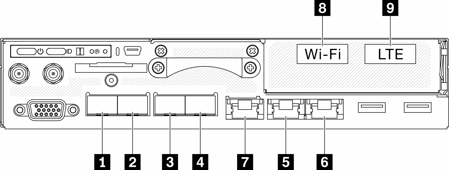
| Physical Ports | Interface Name (Used in Embedded Switch CLI) | |
|---|---|---|
| 1 | 10 GbE SFP+ | N/A |
| 2 | 10 GbE SFP+ | N/A |
| 3 | 1 GbE SFP | eth6 |
| 4 | 1 GbE SFP | eth3 |
| 5 | 1 GbE RJ45 | eth1 |
| 6 | 1 GbE RJ45 | eth2 |
| 7 | 1 GbE RJ45 | eth4 |
| 8 | Wi-Fi | wlan0 |
| 9 | LTE | wwan0 |
Configuration 1:
In configuration 1, most of the ports are used as downlink port (edge port). Server provides maximum capacity of connection for other devices, but without failover protection. LTE and WLAN AP mode are both applicable for usage in this configuration.
| Function | Port |
|---|---|
| Host port | 1 and 2 Two 10Gb Ethernet SFP+ |
| XCC Management port | 7 1Gb Ethernet RJ45 |
| Uplink port (cloud port) | 6 1Gb Ethernet RJ45 9 LTE (an adapter inside the node, not a physical port, default is disabled) |
| Downlink port (edge port) | 3 and 4 Two 1Gb Ethernet SFP 5 1Gb Ethernet RJ45 8 WLAN AP (an adapter inside the node, not a physical port, default is disabled) |
Configuration 2:
In configuration 2, port 3 is used as cluster port (inter-switch port). Server provides redundancy, backup, or other usage depends on setting. LTE and WLAN AP mode are both applicable for usage in this configuration.
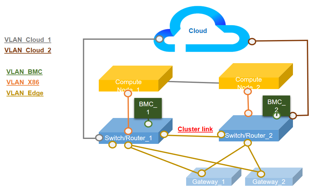
| Function | Port |
|---|---|
| Host port | 1 and 2 Two 10Gb Ethernet SFP+ |
| XCC Management port | 7 1Gb Ethernet RJ45 |
| Uplink port (cloud port) | 6 1Gb Ethernet RJ45 9 LTE (an adapter inside the node, not a physical port, default is disabled) |
| Cluster port (inter-switch port) | 3 1Gb Ethernet SFP |
| Downlink port (edge port) | 4 1Gb Ethernet SFP 5 1Gb Ethernet RJ45 8 WLAN AP (an adapter inside the node, not a physical port, default is disabled) |
Configuration 3:
In configuration 3, port 3 and port 4 are used as cluster port (inter-switch port). Server provides its maximum level of cluster toppology (three servers in maximum). LTE and WLAN AP mode are both applicable for usage in this configuration.
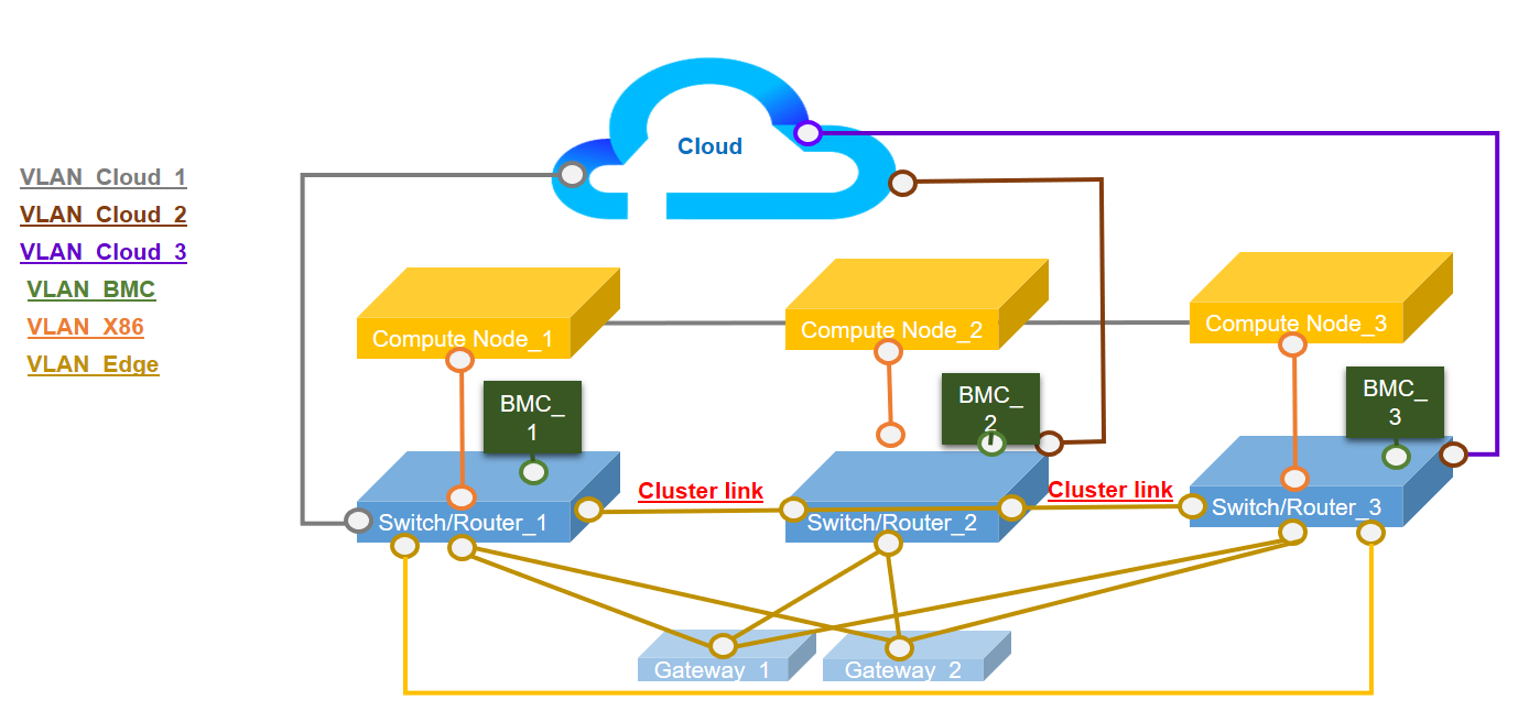
| Function | Port |
|---|---|
| Host port | 1 and 2 Two 10Gb Ethernet SFP+ |
| XCC Management port | 7 1Gb Ethernet RJ45 |
| Uplink port (cloud port) | 6 1Gb Ethernet RJ45 9 LTE (an adapter inside the node, not a physical port, default is disabled) |
| Cluster port (inter-switch port) | 3 and 4 Two 1Gb Ethernet SFP |
| Downlink port (edge port) | 5 1Gb Ethernet RJ45 8 WLAN AP (an adapter inside the node, not a physical port, default is disabled) |
Configuration 4:
In configuration 4, port 8 is used as WLAN client port for failover backup. Server connects to the existing Wi-fi as a client, users can access to Lenovo XClarity Controller through Wi-fi rather than physical wired connection. Only WLAN client mode is applicable for usage in this configuration.
| Function | Port |
|---|---|
| Host port | 1 and 2 Two 10Gb Ethernet SFP+ |
| XCC Management port | 7 1Gb Ethernet RJ45 |
| Uplink port (cloud port) | 6 1Gb Ethernet RJ45 8 WLAN client (an adapter inside the node, not a physical port, default is disabled) 9 LTE (an adapter inside the node, not a physical port, default is disabled) |
| Downlink port (edge port) | 3 and 4 2x GbE SFP 5 1Gb Ethernet RJ45 |
Configuration 5:
In configuration 5, LTE/WLAN function is an optional. Server can work in wired environment.
| Function | Port |
|---|---|
| Host port | 1 and 2 Two 10Gb Ethernet SFP+ |
| Plate (No pre-configured IP setting, ports in plate are like L2 dumb switch) | 3 and 4 1 GbE SFP 5 and 6 1 GbE RJ45 |
| User configuration | 8 WLAN (an adapter inside the node, not a physical port, default is disabled) |
| XCC Management port | 7 1Gb Ethernet RJ45 |
| Uplink port (cloud port) | 9 LTE (an adapter inside the node, not a physical port, default is disabled) |
Configuration 6 (Custom Configuration):
If no configuration is found to meet the requirements, the customized configuration is available. It is best practice to select a preset which is similar to the requirements, and then adjust the setting through Embedded Switch CLI, see example commands in below:
|
Configuration displayin
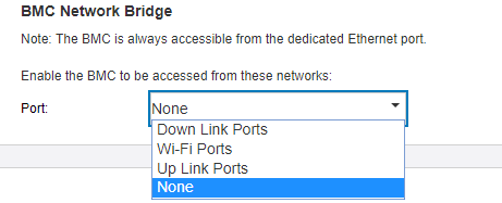
BMC network bridge
BMC network bridge is an configuration to select the outbound interface to access to BMC management port. There are four options as shown below. The default is “None”, which means only management port can access XCC interface.