Installazione del Lenovo Compute Complex Neptune Core Module
Seguire le istruzioni riportate in questa sezione per installare il Compute Complex Neptune Core Module.
Questa attività deve essere eseguita da tecnici qualificati certificati dall'assistenza Lenovo. Non tentare di rimuovere o installare senza una formazione e una qualifica adeguate.
Contattare Lenovo Professional Services il team per assistenza quando si installa la parte per la prima volta.
Informazioni su questa attività

Leggere Linee guida per l'installazione e Elenco di controllo per la sicurezza per assicurarsi di operare in sicurezza.
Spegnere il server e le periferiche e scollegare i cavi di alimentazione e tutti i cavi esterni. Vedere Spegnimento del server.
Tenere le parti sensibili all'elettricità statica negli involucri antistatici fino all'installazione per evitare l'esposizione all'elettricità statica. Maneggiare le parti con un cinturino da polso di scaricamento elettrostatico o un altro sistema di messa a terra. Posizionare le parti su una superficie antistatica.
| Elenco dei tipi di cacciavite dinamometrico | Tipo di vite |
|---|---|
| Cacciavite a testa Torx T30 | Vite Torx T30 |
| Cacciavite a croce 2 | Vite a croce 2 |
Procedura
- Preparare il server.
- Installare il supporto del tubo sullo chassis.Figura 1. Installazione del supporto del tubo
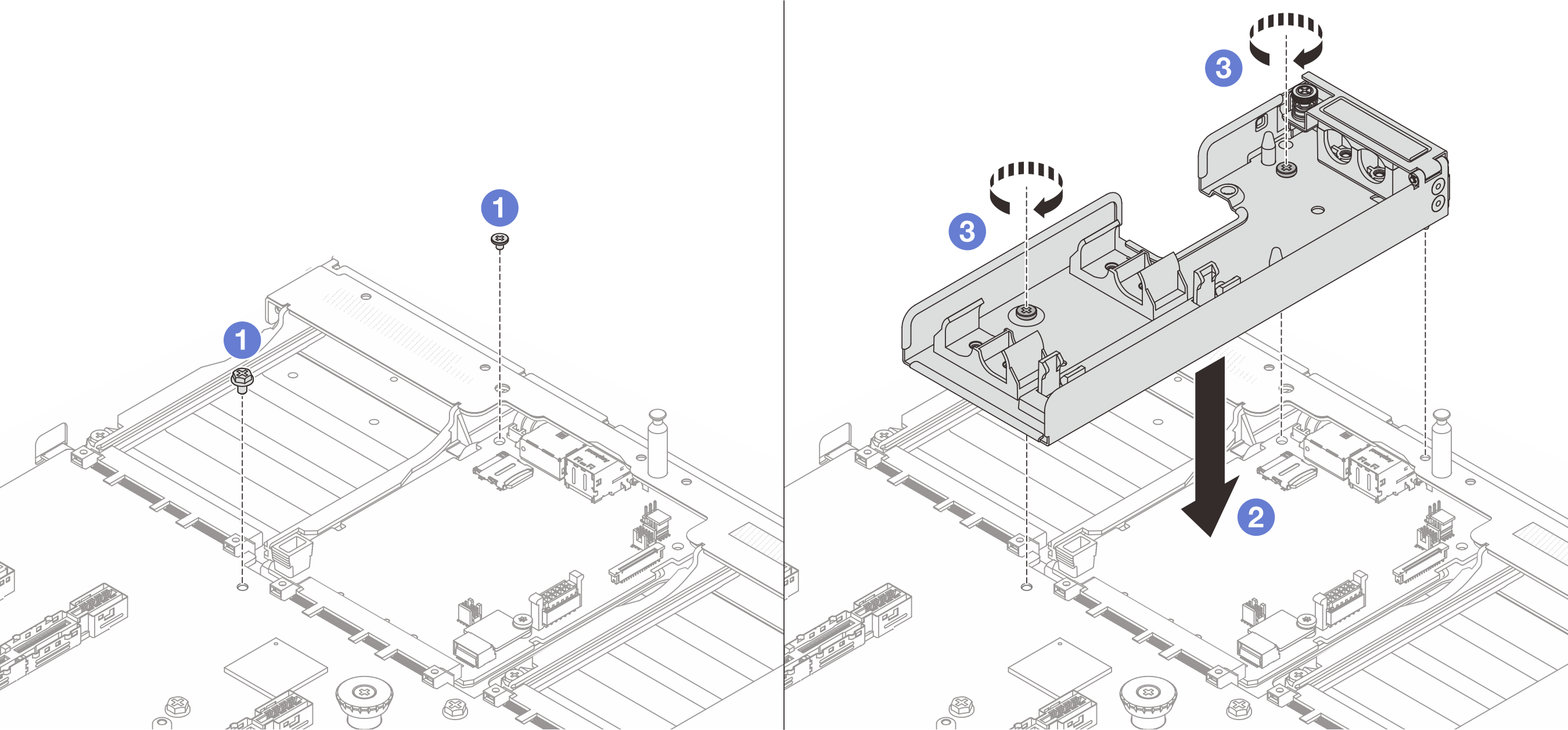
 Allentare la vite sulla scheda I/O di sistema e sulla scheda del processore.
 Allineare i fori per viti sul supporto del tubo alla scheda I/O di sistema e alla scheda del processore. Allineare il piedino della guida del supporto alla parete posteriore.
 Serrare la vite per fissare il supporto alla scheda I/O di sistema e alla scheda del processore.
- Aprire il coperchio del supporto del tubo.Figura 2. Apertura del coperchio del supporto
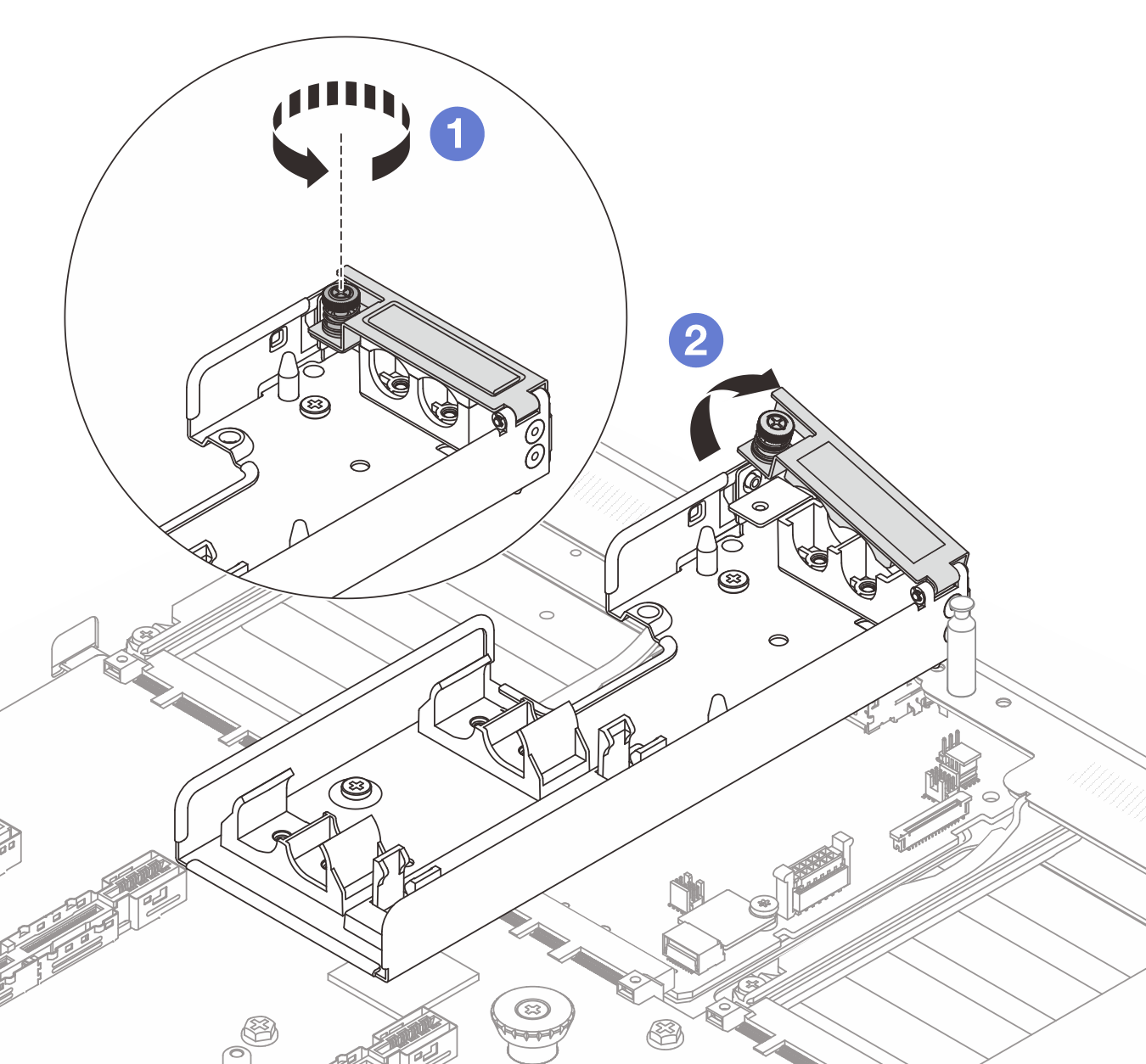
- Allentare la vite zigrinata sul supporto del tubo.
- Aprire il fermo.
- Installare il supporto del tubo sullo chassis.
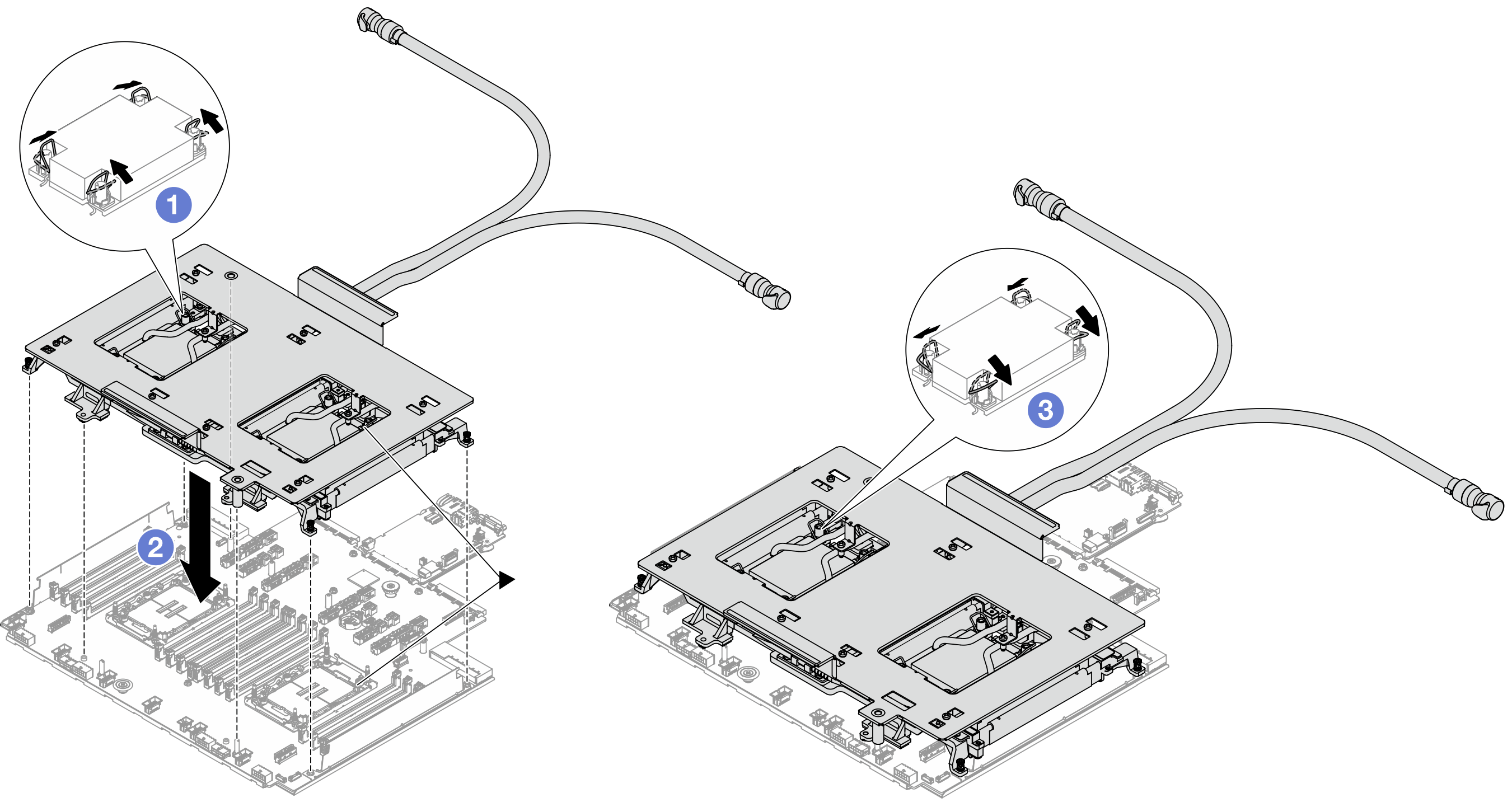
- Installare il processore nel modulo Compute Complex Neptune Core Module. Per ulteriori informazioni, vedere Installazione di un processore e un dissipatore di calore.Figura 3. Installazione del processore
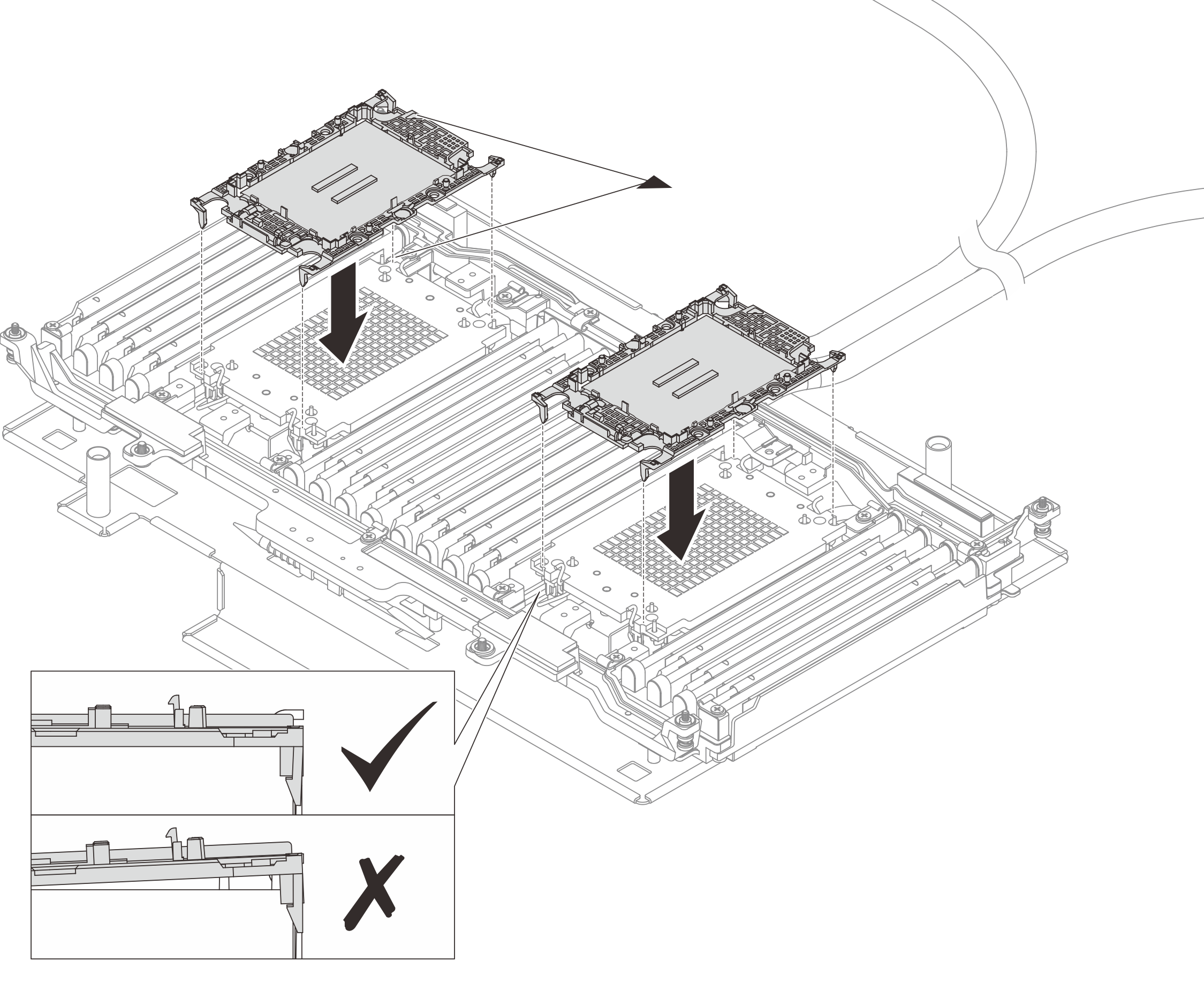
Allineare il contrassegno triangolare sull'etichetta dell'assieme piastra a freddo al contrassegno triangolare sulla piastra del processore e sul processore.
Installare la piastra del processore sul modulo.
Spingere la piastra in posizione fino ad agganciare i fermi in tutti e quattro gli angoli.
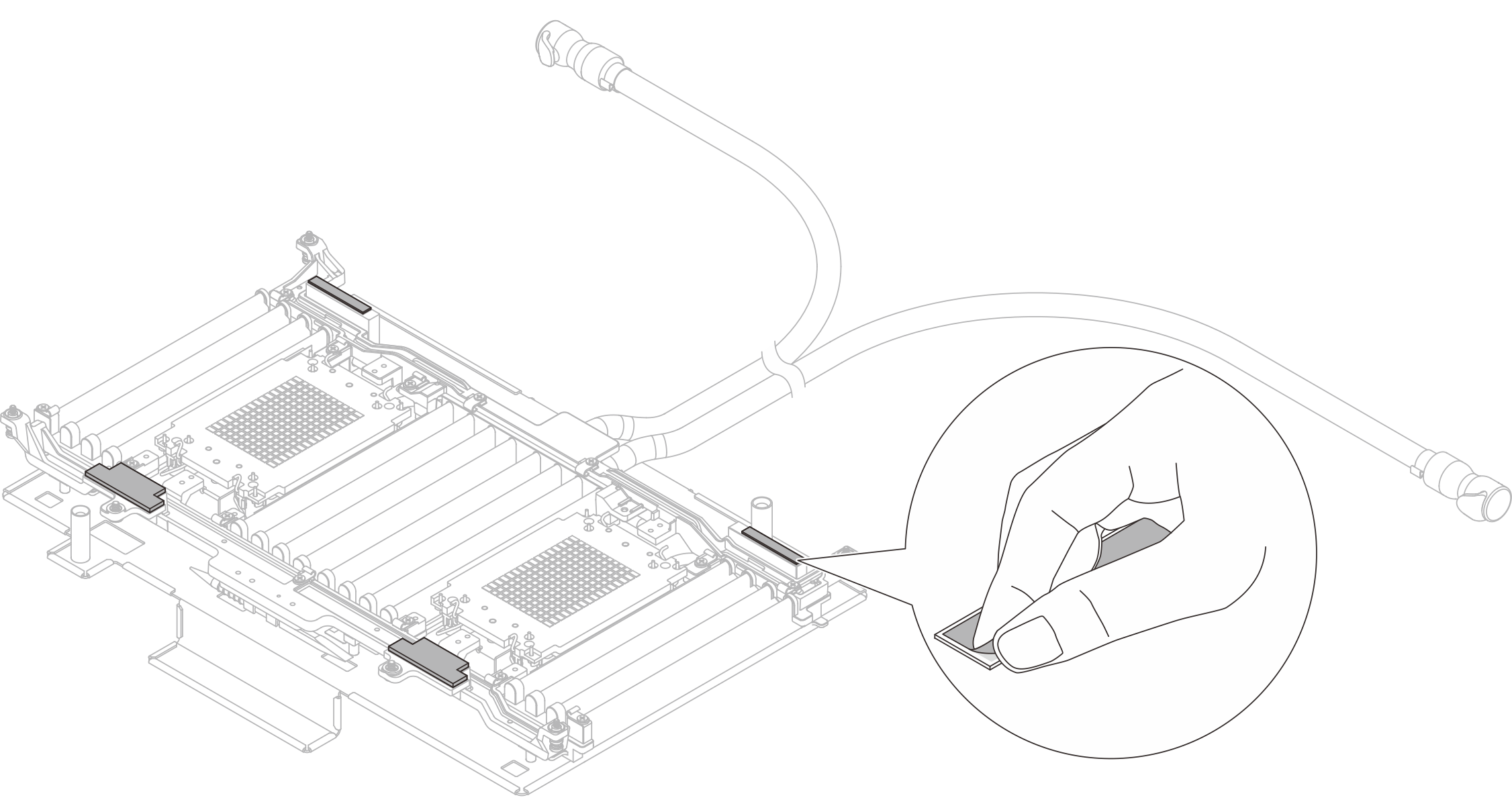
- (Facoltativo) Per installare un nuovo modulo, rimuovere la carta protettiva dei pad termici.NotaSe i pad termici sono macchiati, sono danneggiati o sono andati persi, richiedere le nuove FRU dei pad termici.Figura 4. Rimozione della carta protettiva
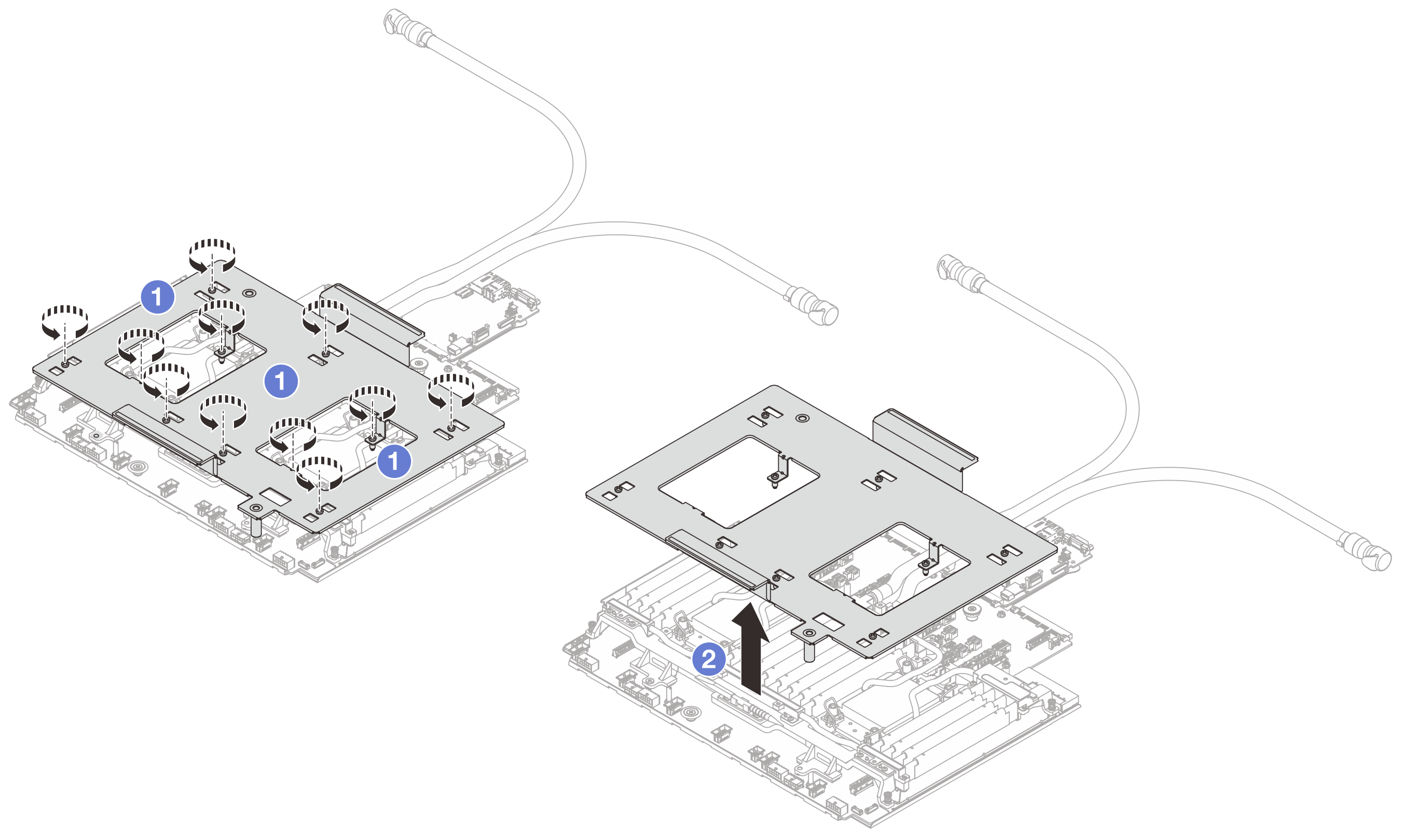
- Installare il modulo del processore sull'assieme della scheda di sistema.Figura 5. Installazione del modulo
- Ruotare i fermi del cavo verso l'interno.
- Allineare il contrassegno triangolare e i quattro dadi Torx T30 sull'assieme piastra a freddo al contrassegno triangolare e ai pioli filettati del socket del processore, quindi inserire l'assieme piastra a freddo nel socket del processore.
- Ruotare i fermi del cavo verso l'esterno finché non si agganciano ai ganci nel socket.
- Rimuovere la confezione di spedizione dal modulo.Figura 6. Rimozione della confezione di spedizione
- Allentare le viti che fissano la confezione di spedizione.
- Separare la confezione di spedizione dal modulo.
- Serrare le sei viti e gli otto dadi Torx T30 sul modulo.NotaGli utenti devono serrare i dadi Torx T30 nella
sequenza di installazione mostrata sull'assieme della piastra a freddo. Serrare completamente le viti, quindi controllare visivamente per verificare che non vi siano spazi tra la vite di spallamento sotto l'assieme della piastra a freddo e il socket del processore. Come riferimento, tenere presente che la coppia richiesta per il fissaggio completo è 0,9-1,3 newton-metri, 8-12 pollici-libbre. Figura 7. Serraggio delle viti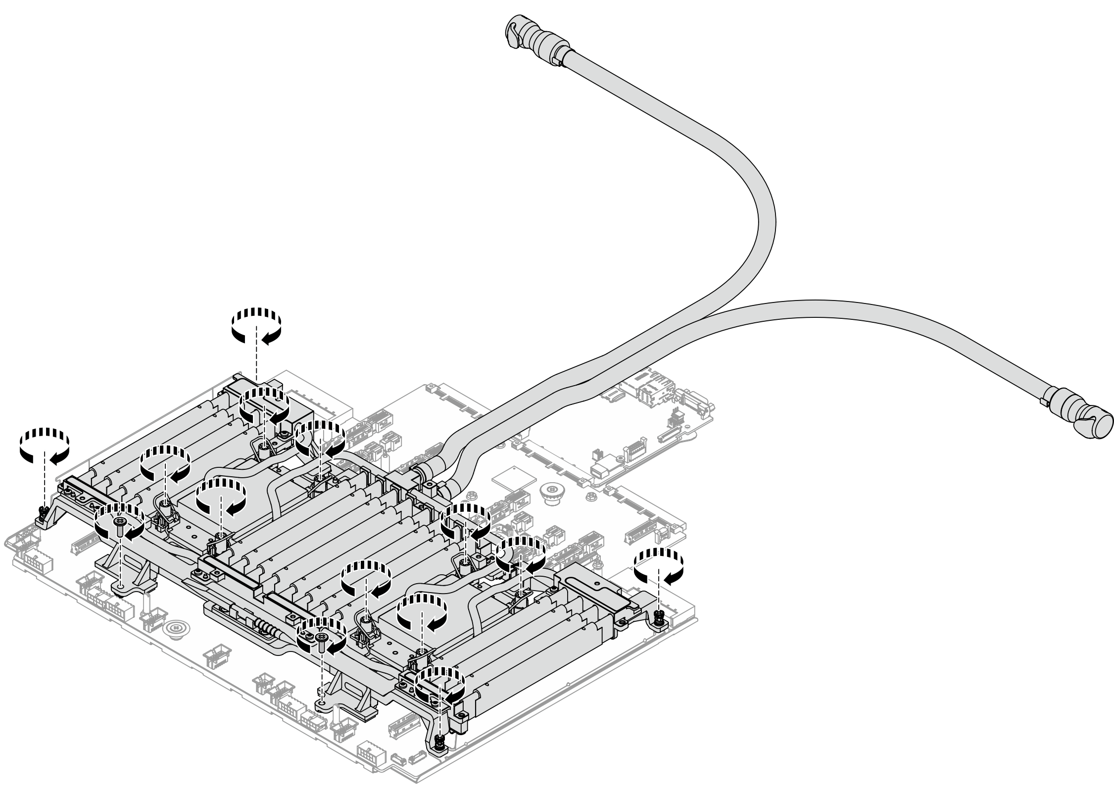
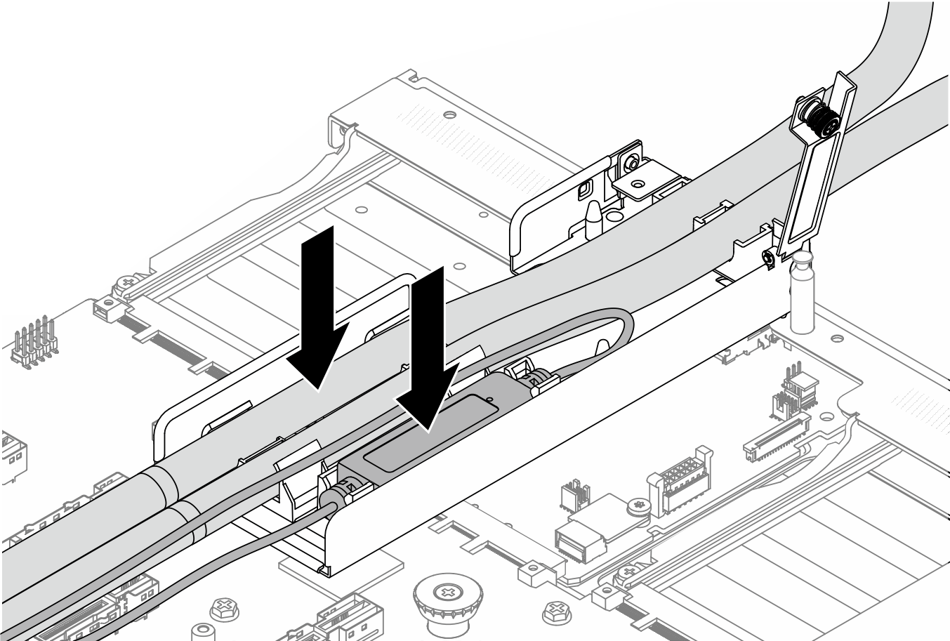
- Posizionare i tubi, il modulo del sensore di rilevamento delle perdite e il cavo.Figura 8. Posizionamento dei tubi e del modulo
 NotaFigura 9. Dettagli dell'installazione
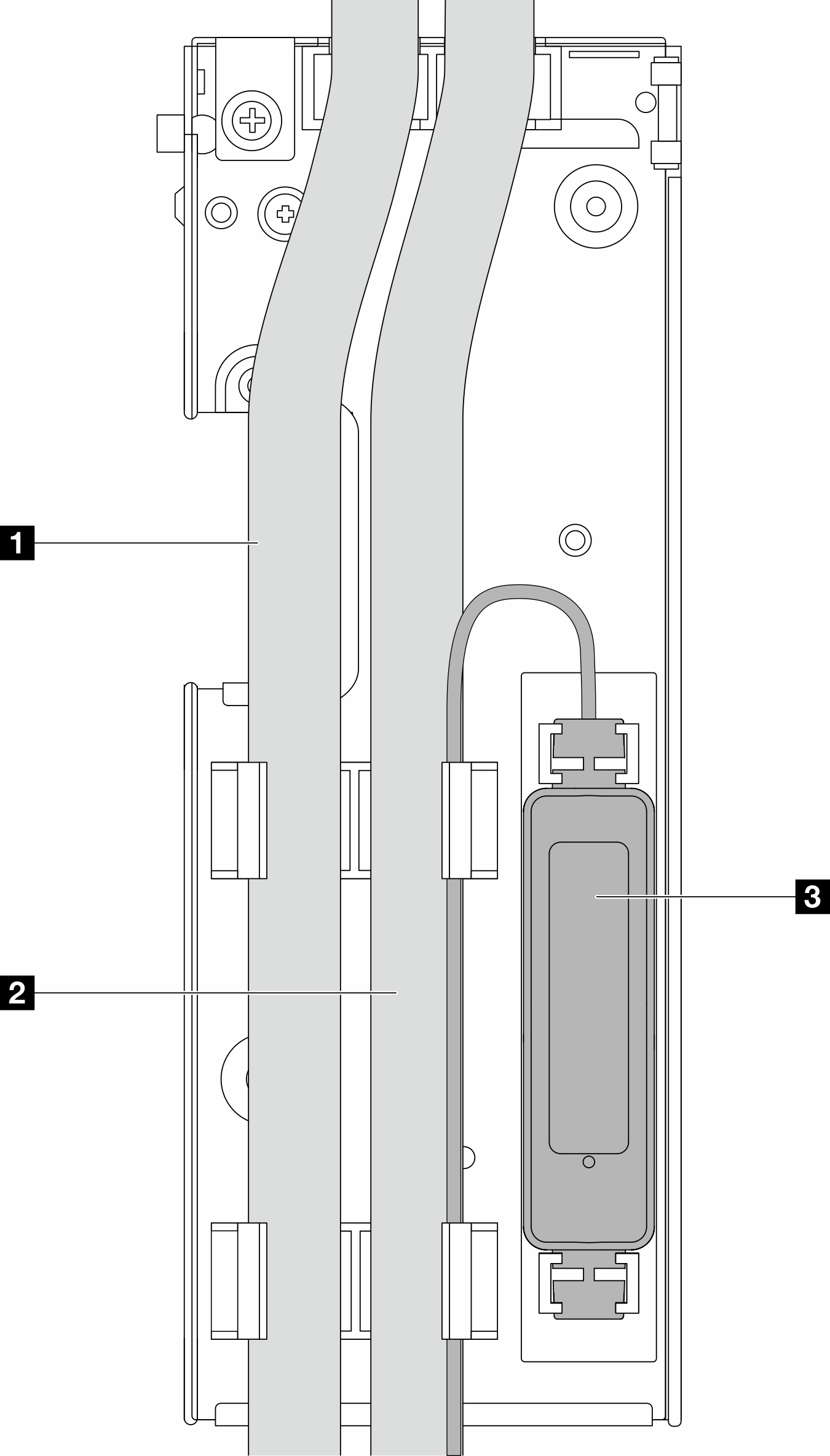
Tubi: posizionare la parte centrale del tubo sul fermo blu e inserire i tubi esterni 1 e interni 2 nel supporto.
Modulo del sensore di rilevamento delle perdite 3: inserire il modulo sul supporto accanto ai tubi. Assicurarsi che il lato con un LED di stato sia rivolto verso l'alto e instradare il cavo come illustrato in precedenza.
NotaNon installare il cavo delmodulo del sensore di rilevamento delle perdite nei fermi del supporto, altrimenti il cavo potrebbe venire danneggiato. Per lo stato di funzionamento del modulo del sensore di rilevamento perdite, vedere LED sul modulo del sensore di rilevamento delle perdite.
- Chiudere il coperchio del supporto del tubo.Figura 10. Richiusura del coperchio
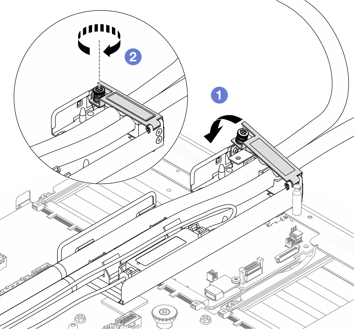
- Chiudere il coperchio e allineare il foro per viti.
- Stringere le viti.
Dopo aver terminato
Completare la sostituzione dei componenti. Vedere Completamento delle operazioni di sostituzione dei componenti.
Video dimostrativo