Install the Lenovo Compute Complex Neptune Core Module
Follow the instructions in this section to install the Compute Complex Neptune Core Module.
This task must be operated by trained technicians that are certified by Lenovo Service. Do not attempt to remove or install it without proper training and qualification.
Contact Lenovo Professional Services team for help when installing the part for the first time.
About this task

Read Installation Guidelines and Safety inspection checklist to ensure that you work safely.
Power off the server and peripheral devices and disconnect the power cords and all external cables. See Power off the server.
Keep static-sensitive parts in their static-protective packages until installation to prevent exposure to static electricity. Handle the parts with an electrostatic-discharge wrist strap or other grounding systems. Place the parts on a static-protective surface.
| Torque screwdriver type list | Screw Type |
|---|---|
| Torx T30 head screwdriver | Torx T30 screw |
| #2 Phillips screwdriver | #2 Phillips screw |
Procedure
- Prepare your server.
- Install the hose holder to the chassis.Figure 1. Installing the hose holder
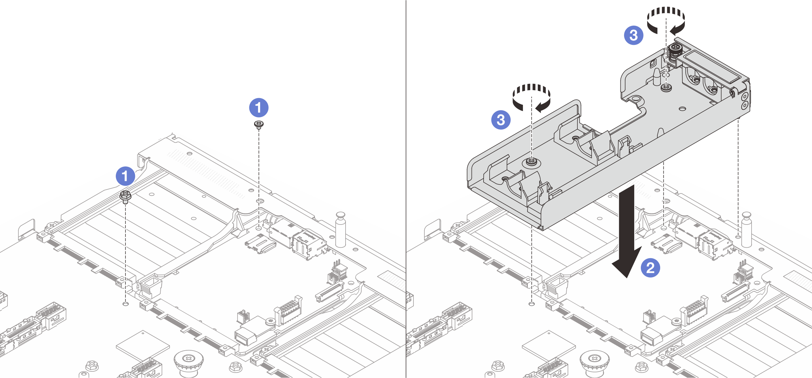
 Loosen the screw on the system I/O board and processor board.
 Align the screw holes on the hose holder to the system I/O board and processor board. And align the guiding pin of the holder to the rear wall.
 Tighten the screw to secure the holder to the system I/O board and processor board.
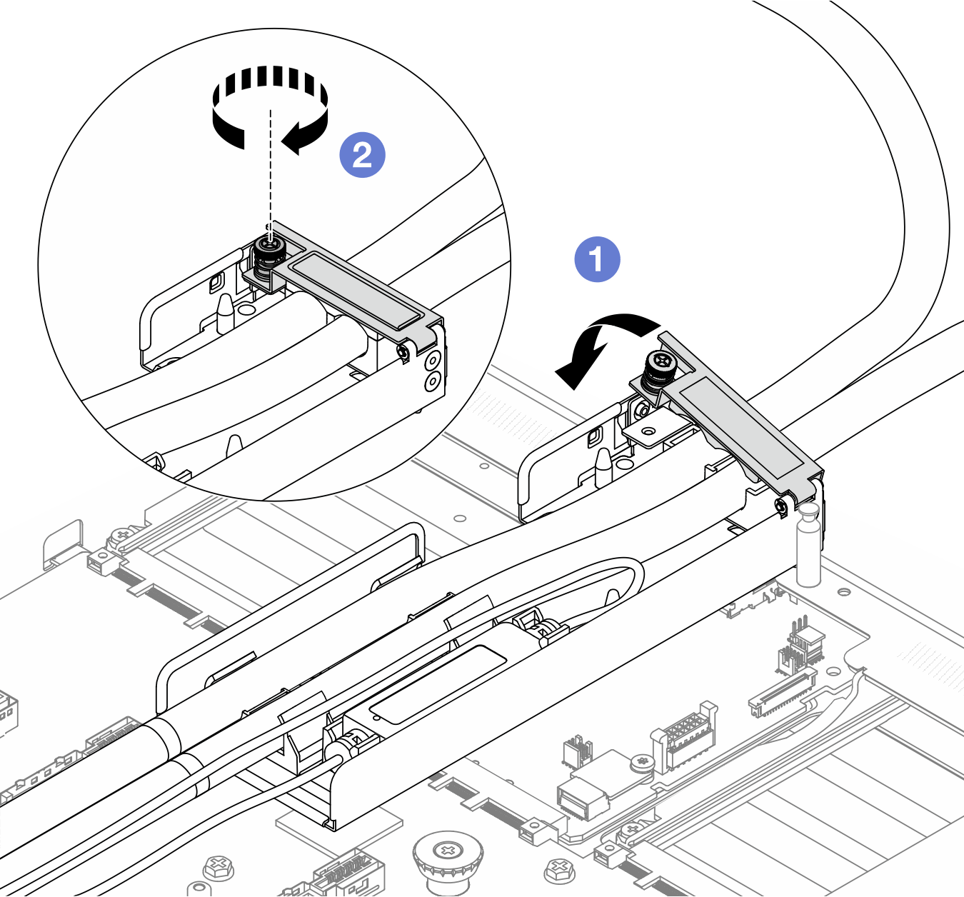
- Open the hose holder cover.Figure 2. Opening the holder cover
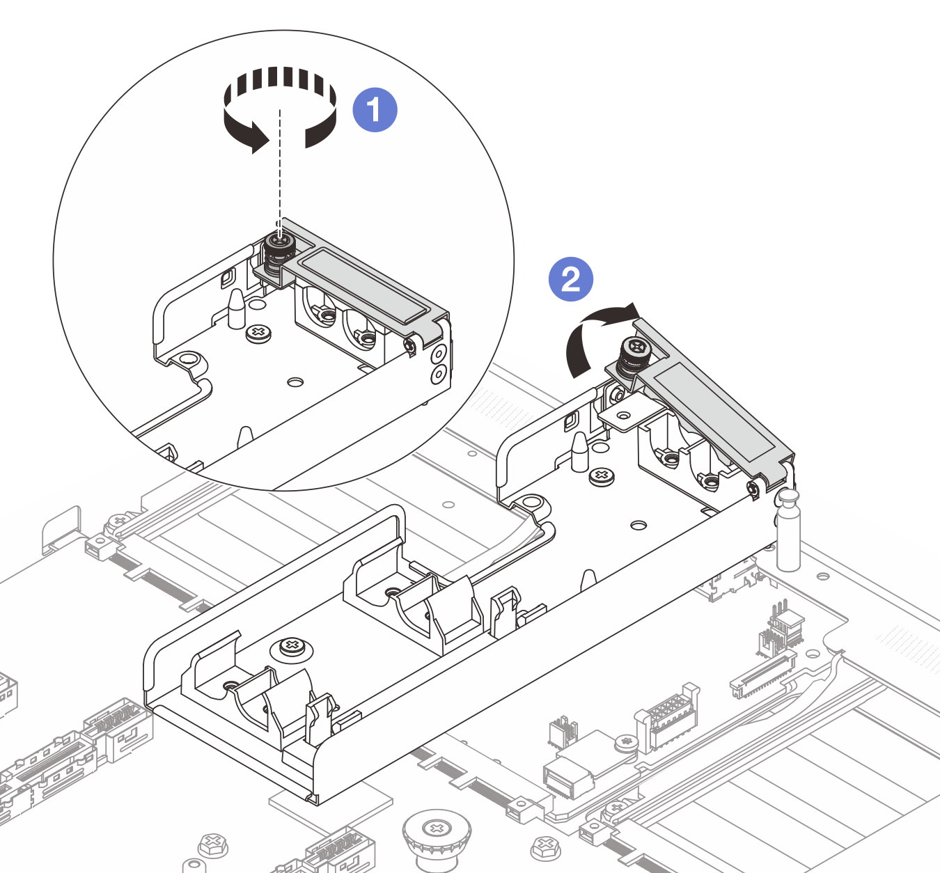
- Loosen the thumbscrew on the hose holder.
- Open the latch.
- Install the hose holder to the chassis.
- Install the processor to the Compute Complex Neptune Core Module. For more information, see Install a processor and heat sink.Figure 3. Installing the processor
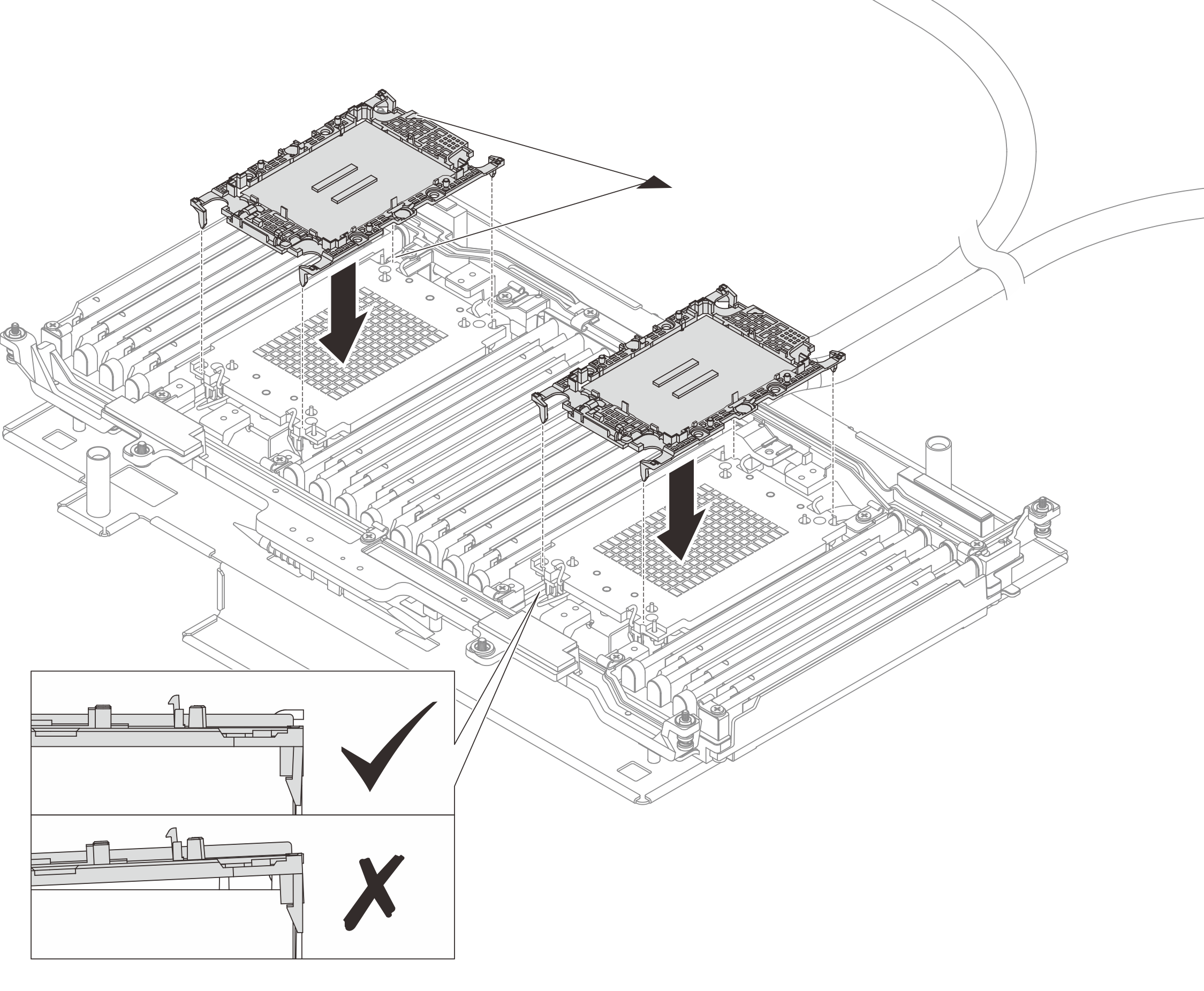
Align the triangular mark on the cold plate assembly label with the triangular mark on the processor carrier and processor.
Install the processor-carrier onto the module.
Press the carrier into place until the clips at all four corners engage.
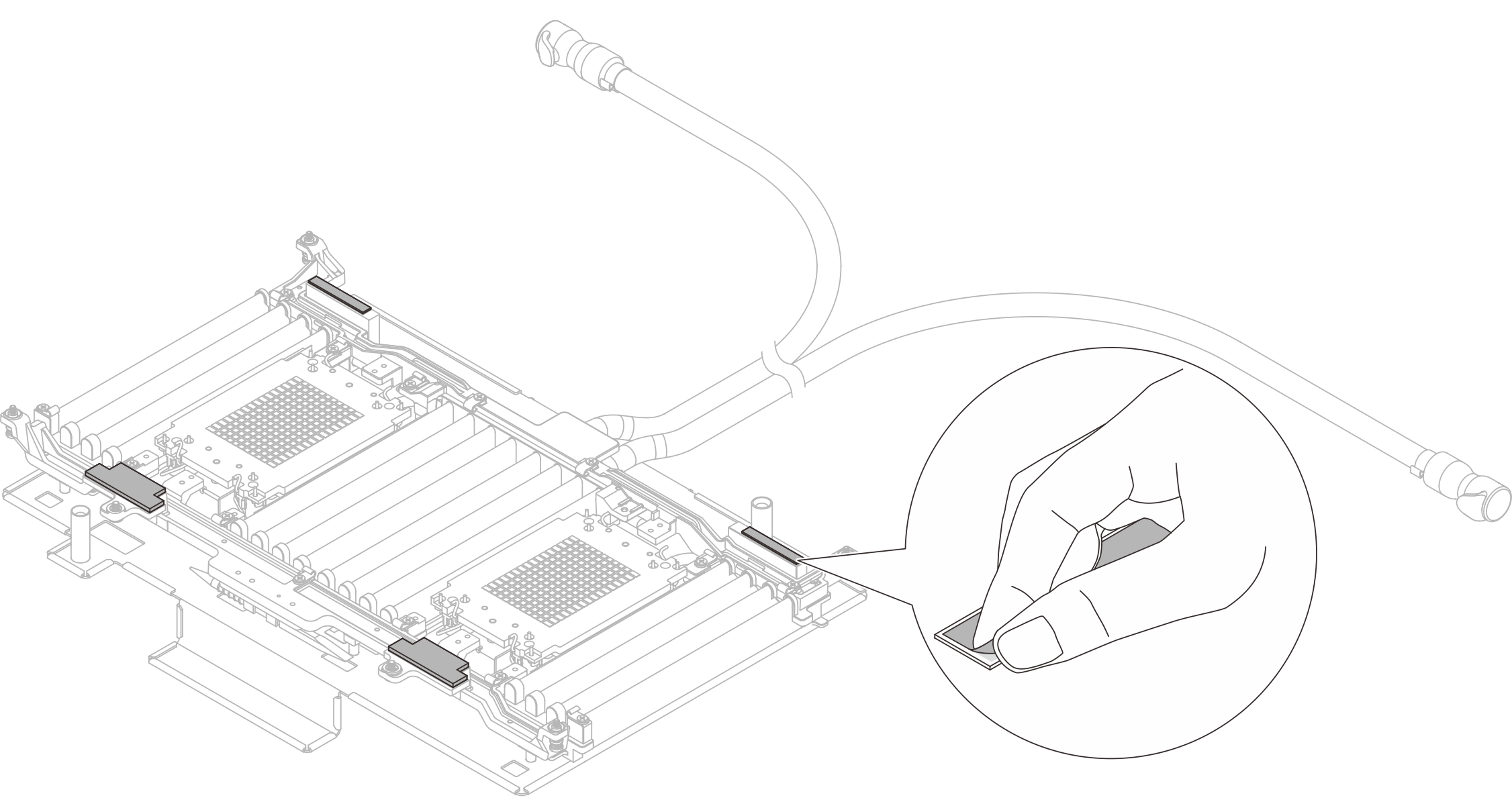
- (Optional) To install a new module, peel off the release paper of thermal pads.NoteIf the thermal pads are stained, damaged or lost, apply for the new thermal pad FRUs.Figure 4. Peeling off the release paper
- Install the processor-module to the system board assembly.Figure 5. Installing the module
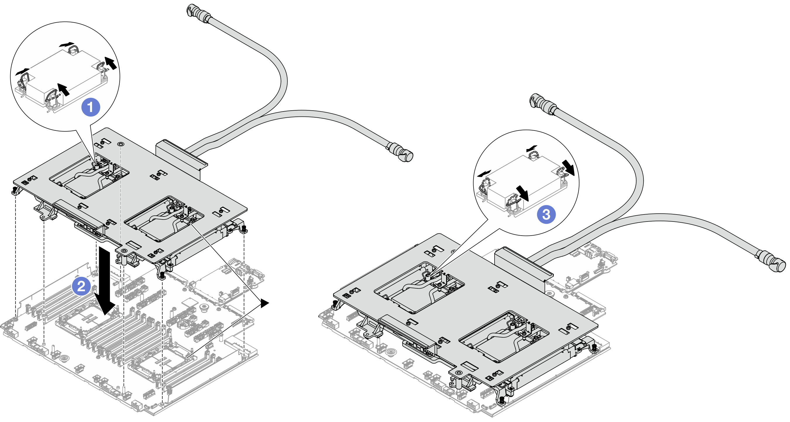
- Rotate the anti-tilt wire bails inward.
- Align the triangular mark and four Torx T30 nuts on the cold plate assembly with the triangular mark and threaded posts of the processor socket; then, insert the cold plate assembly into the processor socket.
- Rotate the anti-tilt wire bails outward until they engage with the hooks in the socket.
- Remove the shipping tray from the module.Figure 6. Removing the shipping tray
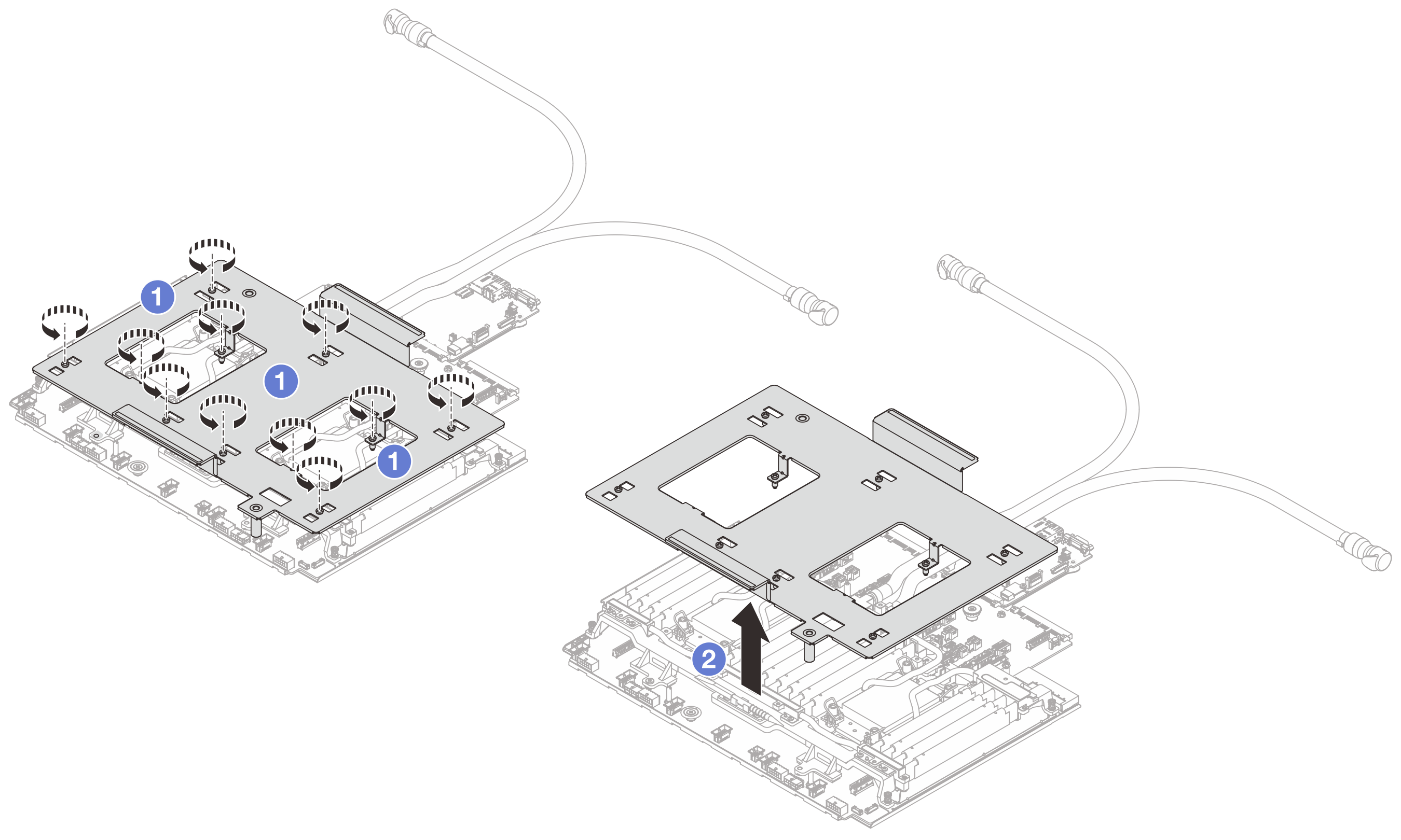
- Loosen the screws that secure the shipping tray.
- Separate the shipping tray from the module.
- Tighten the six screws and eight Torx T30 nuts on the module.NoteUsers should tighten the Torx T30 nuts
in the installation sequence shown on the cold plate assembly. Tighten the screws until they stop; then, visually inspect to make sure that there is no gap between the screw shoulder beneath the cold plate assembly and the processor socket. (For reference, the torque required for the fasteners to fully tighten is 0.9-1.3 newton-meters, 8-12 inch-pounds.) Figure 7. Tightening screws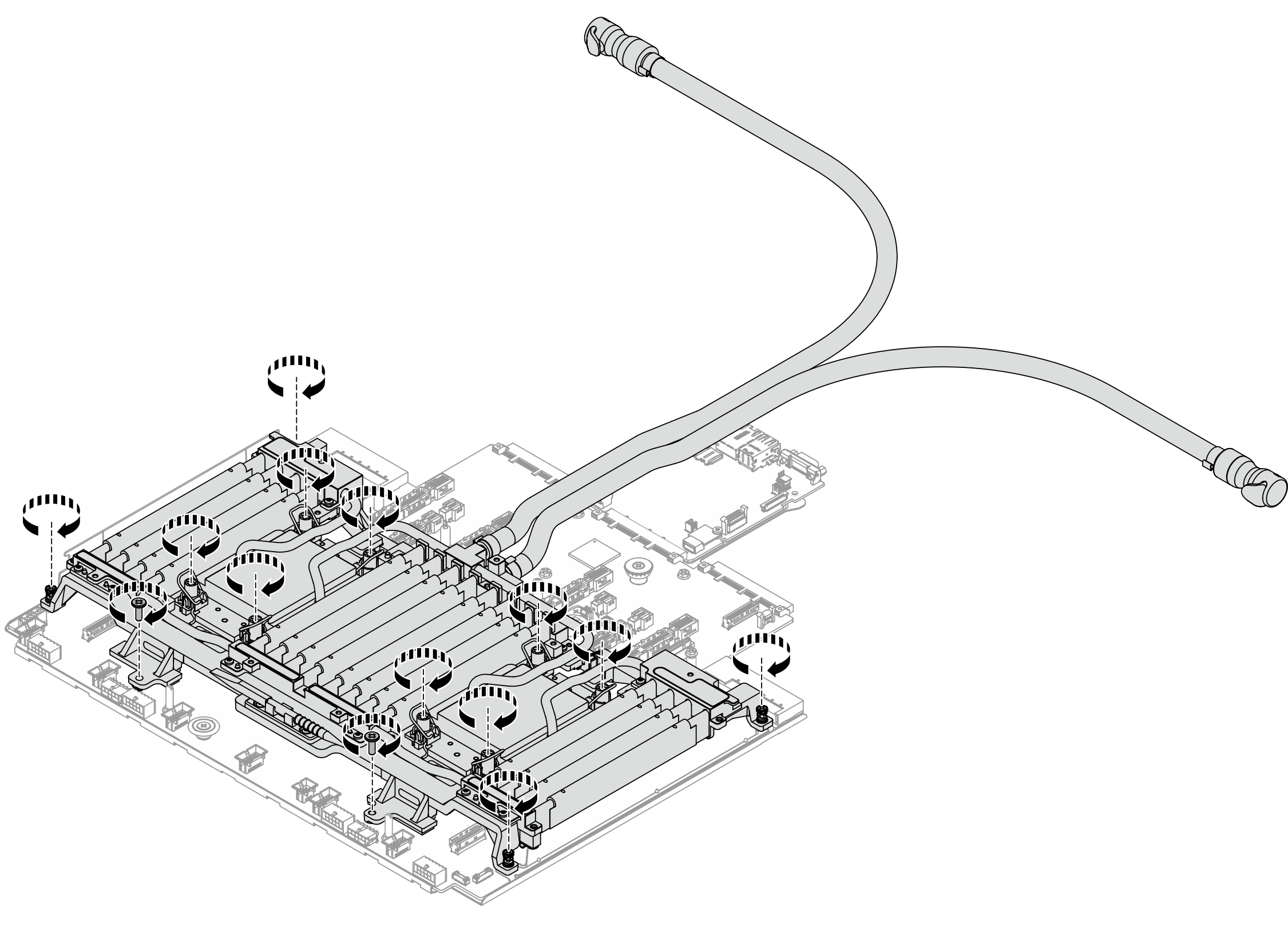
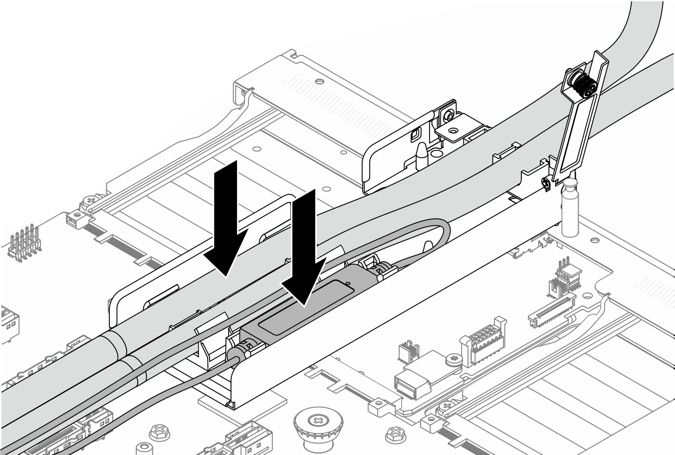
- Place the hoses, the leakage detection sensor module and the cable.Figure 8. Placing the hoses and module
 NoteFigure 9. Installation details
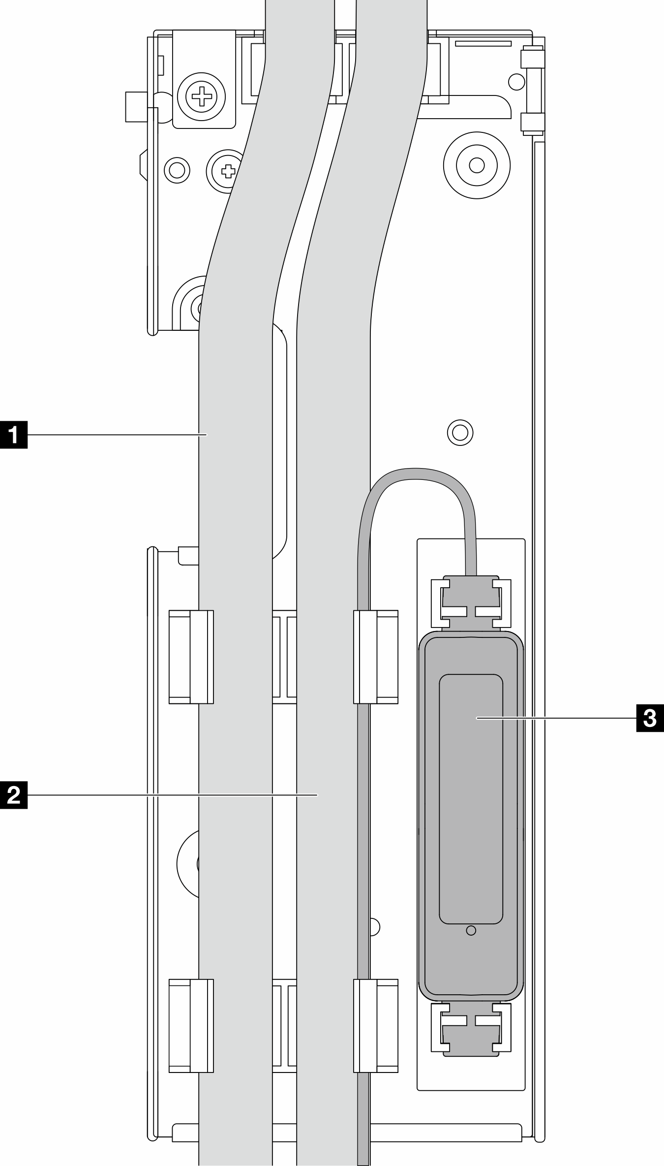
The hoses: place the middle part of the hose against the blue latch; and insert the 1 outlet and 2 inlet hoses into the holder.
The leakage detection sensor module 3: Insert the module to the holder beside the hoses. And make sure that the side with a status LED is up and route the cable as illustrated above.
NoteDo not install theleakage detection sensor module cable into the holder clips; otherwise the cable might be damaged. For leakage detection sensor module working status, see LED on the leakage detection sensor module.
- Close the hose holder cover.Figure 10. Closing the cover back
- Close the cover in and align the screw hole.
- Tighten the screws.