6 x 2.5 吋 SAS/SATA + 2 x 2.5 吋 NVMe + 2 x 2.5 吋 AnyBay 背板(一個處理器)
使用本節瞭解配備十個 2.5 吋前方硬碟和一個處理器的伺服器型號的 AnyBay 背板纜線佈線。
下表顯示背板接頭和處理器板接頭之間的對映關係。
下圖顯示 6 x 2.5 吋 SAS/SATA、2 x 2.5 吋 NVMe 和 2 x 2.5 吋 AnyBay 前方機槽配置的纜線佈線。接頭之間的連接:1 ↔ 1,2 ↔ 2,3 ↔ 3,... n ↔ n
6 x 2.5 吋 SAS/SATA、2 x 2.5 吋 NVMe 和 2 x 2.5 吋 AnyBay 硬碟,以及 1 x 16i/8i SFF RAID 配接卡 (Gen 3/Gen 4) 的纜線佈線
圖 1. 6 x 2.5 吋 SAS/SATA、2 x 2.5 吋 NVMe 和 2 x 2.5 吋 AnyBay 硬碟,以及 1 x 16i/8i SFF RAID 配接卡 (Gen 3/Gen 4) 的纜線佈線
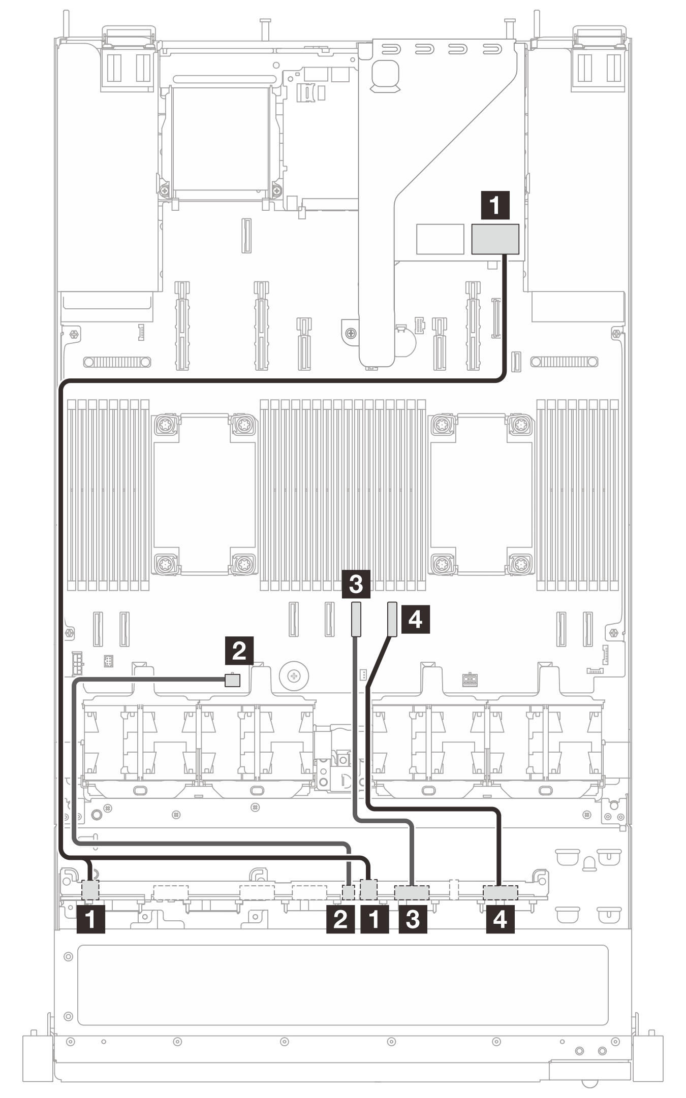
| 從 | 到 | 纜線長度 |
|---|---|---|
| 1 背板上的 SAS 0 和 SAS 1 接頭 | 1
|
|
| 2 背板上的電源接頭 | 2 處理器板上的電源接頭 2A 接頭 | 480 公釐 |
| 3 背板上的 NVMe 6-7 接頭 | 3 處理器板上的 PCIe 接頭 4 | 250 公釐 |
| 4 背板上的 NVMe 8-9 接頭 | 4 處理器板上的 PCIe 接頭 3 | 350 公釐 |
圖 2. 6 x 2.5 吋 SAS/SATA、2 x 2.5 吋 NVMe 和 2 x 2.5 吋 AnyBay 硬碟,以及 1 x 16i CFF RAID 配接卡 (Gen 4) 的纜線佈線

| 從 | 到 | 纜線長度 |
|---|---|---|
| 1 背板上的 SAS 0 接頭 | 1 RAID 配接卡上的 C0 接頭 | 175 公釐 |
| 2 RAID 配接卡上的輸入接頭 | 2 處理器板上的 PCIe 接頭 2 | 450 公釐 |
| 3 背板上的電源接頭 | 3 處理器板上的電源接頭 2A | 480 公釐 |
| 4 背板上的 SAS 1 接頭 | 4 RAID 配接卡上的 C1 接頭 | 150 公釐 |
| 5 背板上的 NVMe 6-7 接頭 | 5 處理器板上的 PCIe 接頭 4 | 250 公釐 |
| 6 背板上的 NVMe 8-9 接頭 | 6 處理器板上的 PCIe 接頭 3 | 350 公釐 |
| 7 RAID 配接卡上的電源接頭 | 7 處理器板上的內部 RAID 電源接頭和電源接頭 13 | 300/800 公釐 |
提供意見回饋