Backplane anteriore + centrale: tre AnyBay a 8 vani + due NVMe a 4 vani da 2,5 pollici
Questa sezione fornisce informazioni sull'instradamento dei cavi per la configurazione (tre backplane dell'unità anteriore AnyBay a 8 vani da 2,5 pollici e due backplane dell'unità centrale NVMe a 4 vani da 2,5 pollici) con una scheda di sistema e due schede switch.
Una scheda retimer e due schede switch
Collegamenti tra i connettori: 1 ↔ 1, 2 ↔ 2, 3 ↔ 3, ... n ↔ n
Figura 1. Instradamento dei cavi di segnale - Parte 1 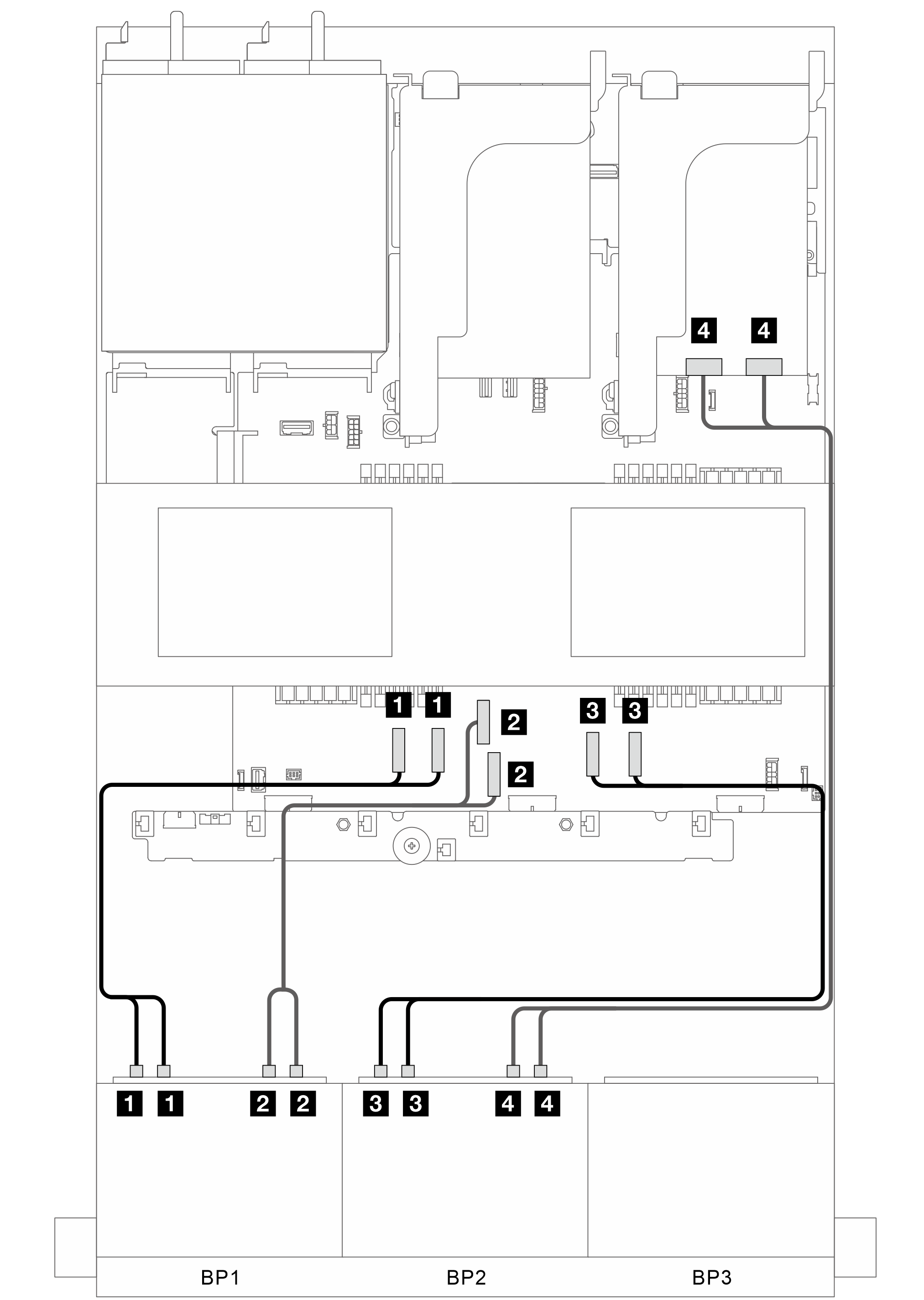 | Figura 2. Instradamento dei cavi di segnale - Parte 2 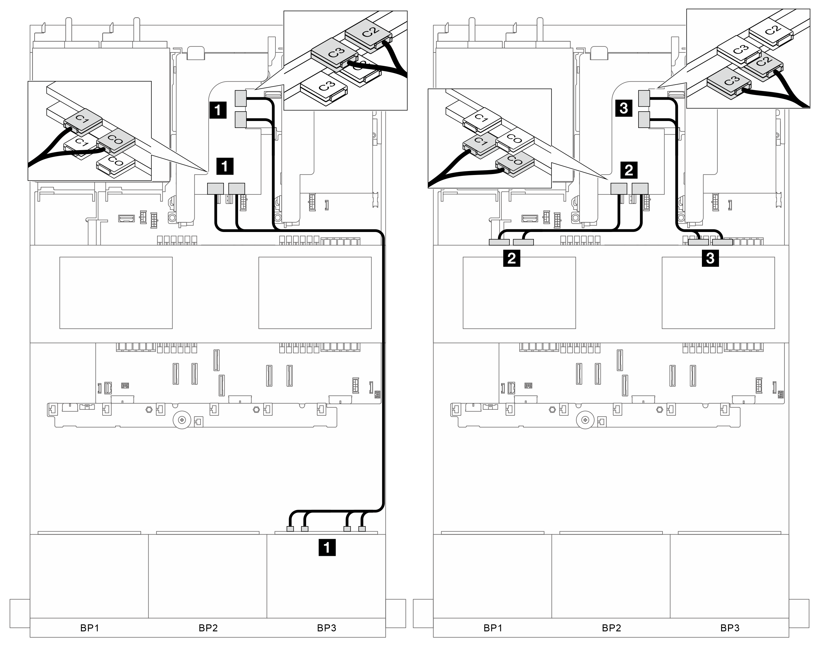 | ||
Da | A | Da | Da |
| 1 BP1: NVMe 0-1, 2-3 | 1 Integrato: PCIe 1, 2 | 1 BP3: NVMe 0-1, 2-3, 4-5, 6-7 | 1 Scheda switch: C0, C1, C2, C3 (slot 4) |
| 2 BP1: NVMe 4-5, 6-7 | 2 Integrato: PCIe 3, 4 | 2 BP5: NVMe 0-1, 2-3 | 2 Scheda switch: C0C1 (slot 5) |
| 3 BP2: NVMe 0-1, 2-3 | 2 Integrato: PCIe 7, 8 | 3 BP6: NVMe 0-1, 2-3 | 3 Scheda switch: C2C3 (slot 5) |
| 4 BP2: NVMe 4-5, 6-7 | 4 Scheda retimer: C0C1 | ||
Envoyer des commentaires